background image

Copyright © D 369 -10/00

28 of 32

Establish the

Problem

Understand the

Sequence of

Operation

Use the Test

Routine

Sketch the

Piping in the

System

Document the

Control

or

Menu Item

Menu Item

Troubleshooting

When troubleshooting any heating system, it is always a good idea to establish a set routine to follow. By following a consistent routine,
many hours of potential headaches can be avoided. Below is an example of a sequence that can be used when diagnosing or
troubleshooting problems in a hydronic heating system.

Establish the problem. Get as much information from the customer as possible about the problem. Is
there too much heat, not enough heat, or no heat? Is the problem only in one particular zone or area of
the building or does the problem affect the entire system? Is this a consistent problem or only
intermittent? How long has the problem existed for? This information is critical in correctly diagnosing
the problem.

Understand the sequence of operation of the system. If a particular zone is not receiving enough heat,
which pumps or valves in the system must operate in order to deliver heat to the affected zone? If the
zone is receiving too much heat, which pumps, valves or check valves must operate in order to stop the
delivery of heat?

Press the 

Test

 button on the control and follow the control through the test sequence as described in the

Testing section. Pause the control as necessary to ensure that the correct device is operating as
it should.

Sketch the piping of the system. This is a relatively simple step that tends to be overlooked, however it
can often save hours of time troubleshooting a system. Note flow directions in the system paying close
attention to the location of pumps, check valves, pressure bypass valves and mixing valves. Ensure
correct flow direction on all pumps. This is also a very useful step if additional assistance is required.

Document the control for future reference. Before making any adjustments to the control, note down all
of the items that the control is currently displaying. This includes items such as error messages, current
temperatures and settings, and which devices should be operating as indicated by the LCD. This
information is an essential step if additional assistance is required to diagnose the problem.

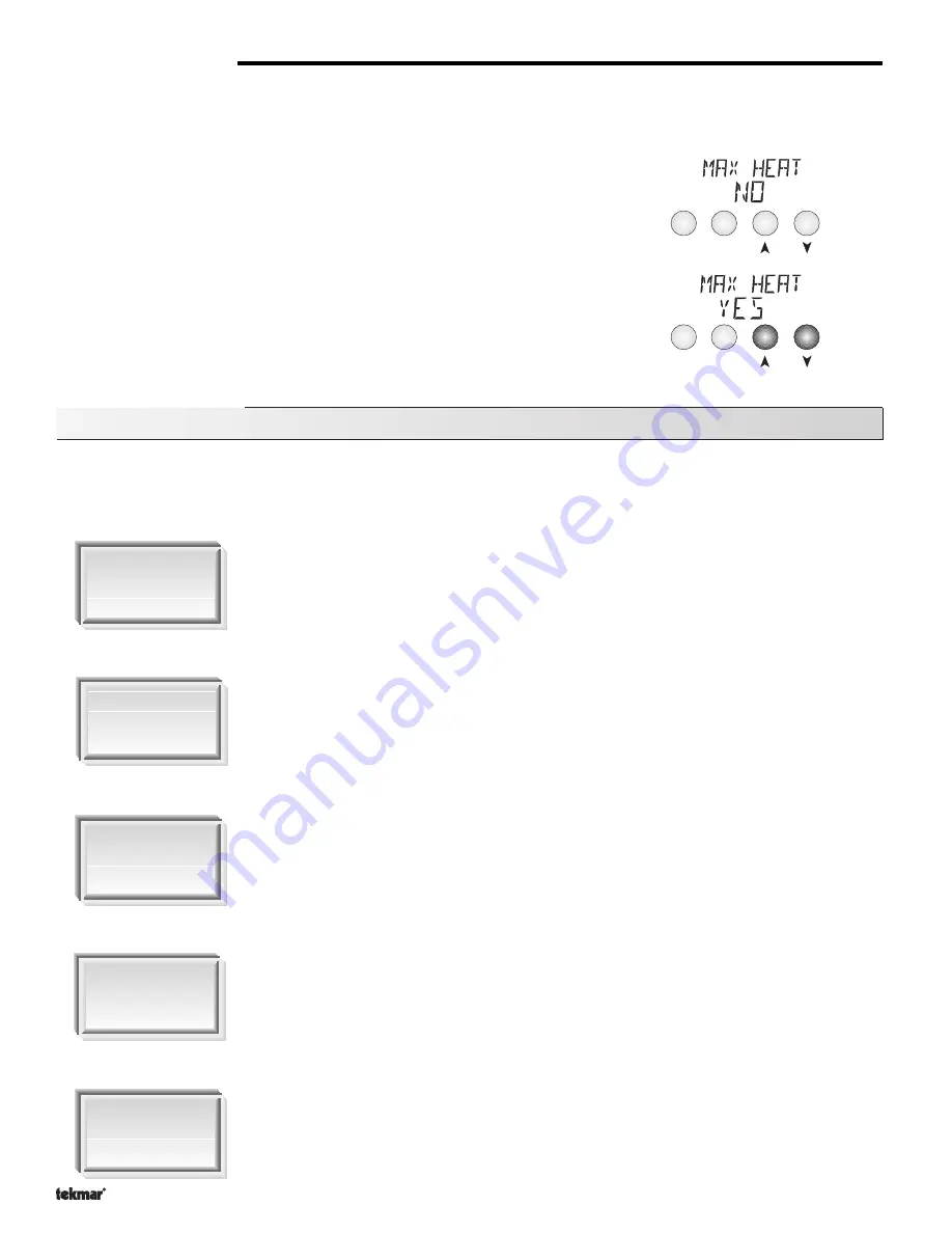
MAX HEAT (MAX HEAT) 

The Zone Control 369 has a function called Max Heat. In this mode, the 369 sets all RTU room temperature settings to 75

°

F (24

°

C)

and turns on the required contacts. The RTU room setting may be adjusted to turn on or off the required zone without delay. The control
continues to operate in this mode for up to 24 hours or until either the 

Item

Menu

 or 

Test

 button is pressed. To enable the Max Heat

feature, use the following procedure.

1) Press and hold the 

Test

 button for more than 3 seconds. At this point, the control

displays the words MAX HEAT and the word NO.

2) Using the Up or Down buttons, select the word YES. After 3 seconds, the control

flashes the word MAX HEAT TEST.

3) To cancel the Max Heat mode, press either the 

Item

Menu

, or 

Test

 button.

4) Once the Max Heat mode has either ended or is cancelled, the control resumes

normal operation.

- 01/09

- 01/09

Summary of Contents for Zone Control 369

Page 1: ...om Temperatue Unit RTU Item Menu Input Indoor Sensor 70 Test None Setback off red red Data Brochure Zone Control 369 D 369 01 09 The Zone Control 369 is designed to control the temperature in up to si...

Page 2: ...Display LCD as the method of supplying information You can use the LCD in order to setup and monitor the operation of your system The 369 has four push buttons Menu Item for selecting and adjusting s...

Page 3: ...access the zone settings for a particular zone select the Zone Adjust menu for that zone by using the Menu button Adjust will be displayed in the left hand side of the display and Zone followed by th...

Page 4: ...d Night mode Ovr Cool AM PM sec min hr Zone Displays when a zone is in operation Optimum Stop Displays when a zone is in optimum stop Optimum Start Displays when a zone is in optimum start Override Di...

Page 5: ...order to prevent short cycling the 369 ensures that the zone relays remain on or off for a minimum amount of time PID Zoning Logic Proportional P Proportional control logic compares the actual zone te...

Page 6: ...contactisoperatedbasedonthezoningdevice s selected RefertotheZONEOUTPUTsectionforsystem pump operation The system pump is also operated based on the purge and exercise functions EXERCISING EXERCISE Th...

Page 7: ...e relay on time increases until it reaches the maximum of the cycle length The Hi stage relay is then turned on and its on time is increased as the load increases When the heating load decreases again...

Page 8: ...ir sensor which is used to control the heating and cooling air temperature while a slab sensor connected to the 063 RTU controls the floor slab temperature During mild conditions the floor slab is mai...

Page 9: ...e Settings section of this brochure Zone Schedule ZONE The zone schedule allows each zone to have its own independent schedule A zone schedule is only available for zones using display RTUs The ZONE s...

Page 10: ...occupied or temporary unoccupied override is selected the 369 operates the zone s in the selected override mode for 3 hours from the time the selection is made Once completed the control reverts to t...

Page 11: ...ther items In cases where a restricted temperature range is required the RTU s range can be limited by changing the access level of the RTU Remote indoor sensors can be connected to the 063 to average...

Page 12: ...ittings Before removing the knockouts check the wiring diagram and select those sections of the chamber with common voltages Do not allow the wiring to cross between sections as the wires will interfe...

Page 13: ...m pump circuit to the Sys Pmp terminal 17 and the second side of the pump circuit to the neutral N side of the 115 V ac power supply Zone Pumps and Zone Valves Note The zoning outputs are isolated ter...

Page 14: ...to the Com and UnO Sw 4 and 1 terminals When these terminals short together the control registers an Unoccupied signal One Stage RTU and Indoor Sensor Connections RTUs and indoor sensors provide indoo...

Page 15: ...or sensor is used connect the two wires from the sensor to the Com and Indr 4 terminals 24 and 27 Note If an RTU is connected to tN1 4 an indoor sensor can not be connected to Indr 4 Zone 6 tN1 6 or I...

Page 16: ...erminals 7 and 6 make sure power to the pump or valve circuit is off and install a jumper between the Com 1 2 and Zn 1 terminals 7 and 6 When the zone circuit is powered up the zone pump should turn o...

Page 17: ...he unlocked position to the locked position As long as the DIP switch is in the locked position the access level of the control or tekmar Net tN1 tN2 device can no longer be viewed or adjusted in its...

Page 18: ...oom air temperature of zone 6 This is the signal that is being received from a zone control OFF 30 to 110 F OFF 1 to 43 C This is the signal that is being sent to a reset or additional zone control OF...

Page 19: ...the zone number in the bottom of the display 369 Zone Adjust Menu 1 of 2 0 10 to 3 00 hr Default 0 30 hr NONE STRT Default NONE 0 30 to 4 00 min Default 3 00 min 0 10 to 2 00 min Default 0 30 min OFF...

Page 20: ...was last cleared The total number of Cooling relay running hours since this item was last cleared The total number of Zn 1 relay running hours since this item was last cleared The total number of Zn 2...

Page 21: ...r will increase if there is a lowering of the input voltage beyond the control s usable range This item can also be used as an indication of the quality of the power source L T D I N S T A D V Range A...

Page 22: ...switch Setback C C C C Occ 2 UnOcc 2 to 11 50 PM or to 23 50 Default to 11 50 PM or to 23 50 Default to 11 50 PM or to 23 50 Default Time when the first occupied period begins every day 7DAY 24h 24hr...

Page 23: ...002 When using display RTUs several items related to the system are no longer available in the control s User Interface These items are available only in the RTU s User Interface Also the number of i...

Page 24: ...tment in the LTD access level MODE OFF and DIP switch Setback The desired cooled room air temperature during an occupied period Note There is only a 3 F 1 C adjustment in the LTD access level RTU 6 an...

Page 25: ...is an adjustable item If the air temperature measured by the RTU drops below this setting the control will display a warning message OFF 20 to 80 F OFF 7 to 27 C Default OFF Note To clear the recorded...

Page 26: ...le refer to the Example given in the Schedule menu of the 369 Note To skip an event during a schedule select the Null event Use the arrow keys to select the Time between 11 50 PM and 12 00 AM is displ...

Page 27: ...utes while the test sequence is paused the control exits the entire test routine If the test sequence is paused the Test button can be pressed again to advance to the next step This can also be used t...

Page 28: ...tch the piping of the system This is a relatively simple step that tends to be overlooked however it can often save hours of time troubleshooting a system Note flow directions in the system paying clo...

Page 29: ...te Access level must be ADV in order to clear the error The control was unable to read a piece of information stored in the Miscellaneous Menu Because of this the control was required to load the fact...

Page 30: ...nu Because of this the control was required to load the factory settings into all of the items in the Adjust menu The control will stop operation until all of the items available in the Adjust menu of...

Page 31: ...o clear the error message The Remote 1 Sensor attached to RTU 1 is being read as a short circuit RTU 1 will continue operation using all remaining sensors If all of the sensors are unavailable the con...

Page 32: ...The purchaser by taking receipt of the tekmar product product acknowledges receipt of the terms of the warranty and acknowledges that it has read and understands same tekmar warrants each tekmar prod...

Reviews: