© 2006
D 480 - 06/06
2 of 8
Table of Contents ............................................................2
User Interface .................................................................2
Sequence of Operation ...................................................3
3 User Buttons .......................................................3
Programming the User Buttons ..............................4
Demand Inputs ...............................................................6
Applications Using Multiple 480 & 481 Together ............7
Error Messages ..............................................................7
Cleaning the User Switch ..............................................8
Warranty .........................................................................8
Table of Contents
User Interface
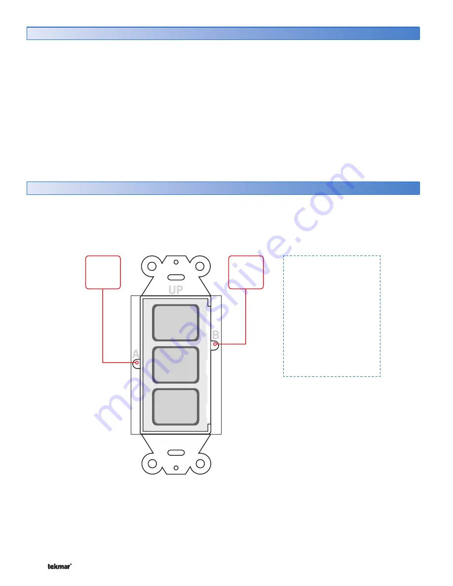
The User Switch has a total of 5 buttons.
User Buttons 1, 2, and 3 allow for users to select the operation of the tN4 system.
Buttons A and B allow the installer to program the operation of User Buttons 1, 2, and 3.
User
Button
1
User
Button
2
User
Button
3
BUTTON
A
BUTTON
B
Factory Defaults:
User Button 1
Scene = 1
Label = Normal
User Button 2
Scene = 3
Label = Unoccupied
User Button 3
Scene = 2
Label = Away


