3
of
12
©
2008 W
544
-
12/08
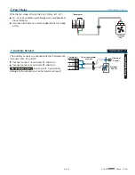
Mounting the Thermostat
If a single or double gang switch box is used, mount the
thermostat directly to the box.
•
Feed the wiring through the openings in the back of the
thermostat.
•
Use the upper and lower screw holes to fasten the
thermostat to the box.
Remove the Wiring Cover:
To remove the wiring cover:
•
Place a small slot screwdriver or similar tool into the slot
located on the right side of the thermostat.
•
While pushing against the plastic tab, lift off the wiring
cover.
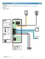
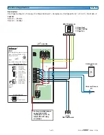
The electrical drawing examples on the following
pages show the 544 in common applications. Choose
the drawing that most accurately depicts the components
in your system and use that drawing as a guide to aid in
wiring your system.
These are only concept drawings, not engineered drawings.
They are not intended to describe a complete system nor
any particular system. It is up to the system designer to
Electrical Drawings
OR
Wiring Symbols
Dry contact switch. Operates a device.
Do not apply power
to these terminals.
Serious control damage will result.
Powered switch. 24 V (ac), switched
output to valve, pump relay etc.
tekmarNet
®
4
Factory jumper.
If a switch box was not used, mount the thermostat directly
to the wall.
•
Feed the wiring through the openings in the back of the
thermostat.
•
Use screws in the upper and lower screw holes to fasten
the thermostat to the wall. At least one of the screws
should enter a wall stud or similar rigid material.
determine the necessary components for and configuration
of the particular system being designed including additional
equipment isolation relays (for loads greater than the
controls specified output ratings) and any safety devices
which in the judgement of the designer are appropriate in
order to properly size, configure and design that system
and to ensure compliance with building and safety code
requirements.
Stud
Thermostat
Base
Terminal
Cover
3
1
/
4
”
(83 mm)
Switch Box
Stud
Wall
Thermostat
Base
Terminal
Cover


