11 of 12
© 2008 W 544 - 12/08
Testing the Wiring
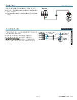
Testing 24 V (ac) Power Supply
1.
Remove the front cover from the thermostat.
2.
Use an electrical test meter to measure (ac) voltage between the R and C terminals. The reading should be 24 V (ac)
+/– 10%.
3.
Install the front cover.
1.
Remove the front cover from the thermostat.
2.
Disconnect the wires from the relay that is to be
tested.
3.
Use an electrical test meter and check for continuity
across the relay.
•
•
When the relay’s symbol is displayed in the LCD,
there should be continuity.
•
•
When the relay’s symbol is not displayed in the
LCD, there should be no continuity.
4.
Reconnect the wires to the relay.
5.
Repeat steps 2 to 4 for each relay that is to be tested.
6.
Install the front cover on the thermostat.
Cool 1
Fan 1
544 LCD Display Segments
Heat 1
Testing the Relays
To test the sensors, the actual temperature at each sensor
location must be measured.
Use a good quality digital thermometer with a surface
temperature probe for ease of use and accuracy. Where
a digital thermometer is not available, place a spare
sensor alongside the one to be tested and compare the
readings.
Testing the Sensors
1.
Remove the front cover from the thermostat.
2.
Disconnect the wires from the sensor that is to be
tested.
3.
Test the sensor’s resistance according to the
instructions in the sensor Data Brochure D 070, D 074
or D 079.
4.
Reconnect the wires.
5.
Install the front cover on the thermostat.
To test the tN4 Network, check the wires for continuity.
1.
Remove the front cover from the thermostat.
2.
Disconnect the two wires (tN4 and C) at one end and
connect them together.
Testing the tN4 Network
3.
Go to the other end of the wires and disconnect them.
4.
Using an electrical test meter, check for continuity.
5.
Reconnect the wires.
6.
Install the front cover on the thermostat.


