TeeJet Legacy 6000 Manual Download Page 89

Chapter 4 - operation

84

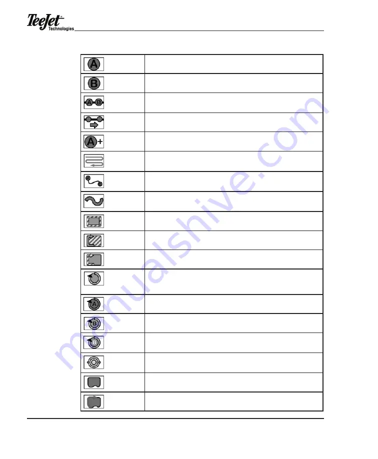
Mark A. Used with Parallel and Curved A-B patterns. Pressed to mark the first point of 

the initial guideline. when pressed, changes to the mark B softkey.

mark B. used with Parallel and Curved a-B patterns. Pressed to mark the end point of 

the initial guideline. when pressed, changes to the New guideline softkey.

New guideLine. displayed after the initial guideline has been created. when pressed, 

changes to the mark a softkey and guidance is disabled until a new guideline is cre-

ated by pressing mark a followed by mark B.

Switch guideline. displayed when more than one guideline has been created.

a+ Shift a-B guideline. displayed when a guideline has been created. use this button 

to shift the a-B line to the current vehicle position.

Straight-Line Parallel guidance. indicates current guidance pattern is straight-line par-

allel. Initial guideline is defined by marking Points A and B. When pressed, launches 

menu to select different guidance mode (e.g., headland, Circle Pivot).

Curved a-B guidance. indicates current guidance pattern is Curved a-B. the initial 

guideline is defined by marking Points A and B. When pressed, launches a menu to 

select a different guidance mode (e.g., headland, Circle Pivot).

headland guidance. indicates the current guidance pattern is headland mode. when 

pressed, launches a menu to allow the selection of a different guidance mode such as 

Straight-line or Circle Pivot.

Ignore Headland Guidance. When pressed, data identified using the Headland On and 

headland off softkeys are excluded from vehicle guidance. 

Headland On. When pressed, any applied data collected is considered part of the field 

headland. 

headland off. when pressed, any applied data collected is not considered part of the 

field headland. 

Circle Pivot guidance. indicates the current guidance pattern is Circle Pivot. the initial 

guideline is defined by marking Points A and B along a circle. When pressed, launches 

a menu to allow the selection of a different guidance mode such as headland or 

Straight-Line.

Circle Mark A. Used with the Circle Pivot pattern. Pressed to mark the first end point of 

the initial circle guideline. when pressed, changes to Circle mark B.

Circle mark B. used with the Circle Pivot pattern. Pressed to mark the end point of the 

initial circle guideline. when pressed, changes to New Circle guideline.

Circle mark B wait. appears when Circle mark a has been pressed and the software 

is collecting enough points (approximately 12 seconds) to describe a circle. after ap-

proximately 12 seconds, this is replaced by the Circle mark B softkey.

Switch Circle guideline. appears when the guidance mode is Circle Pivot and there 

is more than one circle guideline created. allows the selection of a different existing 

circle guideline.

Map Field Boundary Off. When displayed, the field boundary is not being mapped. 

when pressed, changes to map Field Boundary on.

Map Field Boundary On. When displayed, the field boundary is being mapped and 

stored to a file. When pressed, changes to Map Field Boundary Off.

Summary of Contents for Legacy 6000

Page 1: ......

Page 2: ...19 GPS Receiver Setup 20 Implement Setup 21 Channel Setup 24 Channel Favorite 25 Application Type 26 Application Type Settings 27 Drive Type 28 Drive Type Settings 28 Units 31 Primary Sensor 32 Primar...

Page 3: ...tomatic Boom Section Control 61 Swath Manager Lookahead 61 Swath Manager 0 50 and 100 Settings 62 Swath Manager Boom 50 and 100 Settings 63 CAN Switchbox 63 Input Status Module ISM 64 Swath Manager 5...

Page 4: ...5 Mark A 95 Mark B 96 Circle Pivot Guidance Navigation 96 FieldPilot 98 Lightbar 99 Curved Guidance 99 Applied Area Detection 100 Previously Applied Area Detection 100 Neighboring Swath Detection 101...

Page 5: ...ta Mode 133 Rate Control Mode 134 Running Implement Setup With a Rate Controller 135 Entering Implement Width 135 Entering Offset Direction Y 136 Entering Offset Distance Y 137 Implement Setup Complet...

Page 6: ...lel Curved A B and Center Pivot Single console in the cab with a single cable connection to the console Simplified operation of product control and GPS record keeping Auto boom section shutoff using S...

Page 7: ...interconnected without large expensive and troublesome wiring harnesses Within a CAN system each module contains its own microprocessor All modules share a standard protocol or communication sequence...

Page 8: ...system Control outputs can be bidirectional or Pulse Width Modulated PWM One DCM is required for every two products to be controlled Figure 1 1 Dual Control Module DCM Swath XL Lightbar The Swath XL...

Page 9: ...on control expandable to 20 Figure 1 3 Switch Function Module SFM CAN Switchbox The CAN Switchbox is used when existing switches are not present in the vehicle and is nearly always used in conjunction...

Page 10: ...the voltage switch state into messages on the CAN Bus Boom valves are connected directly to these same switches or are alternately driven by a Switch Function Module on the CAN bus Figure 1 5 Input S...

Page 11: ...Manager 5 or an Input Status Mod ule or a CAN Boom Switchbox typically one per system Legacy 6000 Configurations The following diagrams are reflective of typical Legacy 6000 configurations Due to the...

Page 12: ...9 Single Channel Liquid Flow Meter Configuration w Swath Manager 5 Figure 1 10 Single Channel Liquid With AutoBoom Shutoff SFM and Switchbox 45 053 40 45 08106 CA N 45 05340 45 08106 CAN 1 3 4 5 2 Co...

Page 13: ...8 Figure 1 11 Single Channel Granular Spreader Figure 1 12 Dual Channel Granular Spreader 45 053 40 45 08106 CA N IS M C ontrol C able 4 5 07 6 02 D C xx xx 45 053 40 45 08106 CA N IS M C ontrol C abl...

Page 14: ...Legacy 6000 98 05053 R2 9 Figure 1 13 Carrier Plus Three Pump Injection System 45 053 40 45 08106 45 08106 CA N CA N...

Page 15: ...Chapter 1 Introduction 10...

Page 16: ...en supplied Figure 2 1 Legacy 6000 Console NOTE When powering the Legacy console ON or OFF press the Power ON OFF button for 1 2 seconds then release the button and wait approxi mately 10 seconds for...

Page 17: ...the system 1 Press the orange Power button located on the bottom left side of the console Launcher the first page of the Legacy 6000 system will be displayed 2 A message indicating a CAN Bus change ha...

Page 18: ...the screen by using the Ar row keys and press the Enter button 4 Turn the channel on YES if in use Set a unique ID number for each channel channel one is typically set to ID 1 Figure 2 4 Channel Assig...

Page 19: ...each channel For new installations choose YES Reset will occur once the last channel is configured and the Forward Arrow softkey is executed to exit Channel Setup Figure 2 6 Reset CAN Bus to Factory...

Page 20: ...with a particular theme e g GPS Receiver Setup Typically a setup wizard guides the operator through the setup process for each specific topic Sub group buttons display only those param eters associate...

Page 21: ...2 10 Example of Parameter Page Data entry on parameter pages is accomplished by the following procedures 1 Highlight the desired character space and use the Arrow keys to scroll through the alphanumer...

Page 22: ...254 1 00 10 0 100 463 etc Figure 2 11 Example of Alphanumeric Data Entry System Setup System Setup allows for the configuration of the Legacy 6000 To access the Sys tem Setup page press the System Se...

Page 23: ...6000 to be configured to match the GPS receiver Defines vehicle or implement parameters including width number of swaths number of boom sections and width of boom sections Configures each Channel tha...

Page 24: ...the speaker volume Date Format Defines the date format displayed MM DD YY or DD MM YY System Date Sets the system date Time Format Defines the time format displayed on the console 12 hr or 24 hr Syst...

Page 25: ...ge Sets the distance prior to an impending hazard that the operator is notified Hazard must have already been mapped Parallel MSG 1 Parallel MSG 2 Parallel MSG 3 Defines which of several lightbar mess...

Page 26: ...bit settings Stop Bits Defines the selected COM port stop bit settings Parity Defines the selected COM port parity Implement Setup Implement Setup defines the number of swaths number of sections per s...

Page 27: ...sections are complete Offset Direction Y The direction along the center line of the vehicle from the GPS antenna to the center of the swath FORWARD BACK Offset Distance Y Distance from the GPS antenn...

Page 28: ...nal Implement Setup page is the Fin ish page Review the configuration by pressing the Review softkey and confirm the setup parameters Press the Forward Arrow softkey to save and apply the imple ment s...

Page 29: ...vigating through these types of screens Many parameters in Channel Setup are dependent on other parameters in Chan nel Setup therefore navigating these settings via the Setup Wizard type interface is...

Page 30: ...will prevent the operator from setting up the Channel every time the application changes Select the favorite for the application using the Arrow keys and press the Finish Flag softkey to apply the se...

Page 31: ...this page There are five possible application types Liquid Granular Seeder NH3 Motor For each application type there is an additional Settings page To access the Set tings page press the Settings soft...

Page 32: ...in Figure 2 19 Configuration Defines the relationship between the sensor and the product Standard Liquid Standard Granular Split Granular application Material shaft speed does not change as booms are...

Page 33: ...tings Description Servo Application rate is controlled by a bidirectional motorized valve PWM Application rate is controlled by a pulse width modulated hydraulic valve or a DC motor Injection Applicat...

Page 34: ...Master Hold Control valve will hold in the same position Closed Control valve will drive full closed Implement Status Control valve response to when the Implement Status switch is open OFF Hold Con t...

Page 35: ...l valve response to all booms OFF Hold Control valve will hold in the same position Closed Control valve will drive full closed and start backup at minimum duty cycle Resume Control valve will close w...

Page 36: ...ed or Distance based These parameters should be established prior to selecting the units of measurement To access the Control Basis page from the Units page press the Settings softkey The operator wil...

Page 37: ...a Distance Time fl oz ac fl oz 1000 ft2 fl oz 100 yd2 l ac fl oz lmi fl oz min l ha l 100 m2 l lkm liters per lane km l min Primary Sensor The Primary Sensor is used for principal control functions an...

Page 38: ...other Primary Sensors Pres sure Digital and Pressure Analog have initial settings as well as sub settings To access the sub settings locate the two Sub Settings softkeys on the right side of the scree...

Page 39: ...es being used at 10mph and 30psi 10 km h 2 bar for metric applications regardless of the actual speed and pressure at which the machine will be operated Table 2 15 Pressure Digital and Analog Sub Sett...

Page 40: ...Figure 2 29 Secondary Sensor Sub Settings Table 2 16 Secondary Sensor Sub Settings Settings Description Input Defines digital and analog sensors Sensor inputs A D are digital Flowmeter and slot senso...

Page 41: ...nitors Select the monitor s used and press the Forward Arrow softkey to save the settings If there is no monitor select the None setting and continue to the next page Figure 2 30 Monitor Page Table 2...

Page 42: ...ate the two Sub Settings softkeys on the right side of the screen Use the two softkeys to toggle between the screens Refer to Table 2 18 for a description of the sub settings Once the sub settings and...

Page 43: ...before triggering an alarm Alarm Status Off disabled Low sensor state goes low to trigger alarm Contact the sensor or machine supplier for this information High sensor state goes high to trigger alar...

Page 44: ...for future use e g My Sprayer Names are entered using the Arrow keys Use the Up and Down Arrow keys to scroll through alphanumeric characters Use the Left and Right Arrow keys to move to the next cha...

Page 45: ...to save the settings FieldPilot Setup FieldPilot Setup defines settings used to fine tune the assisted steering system Settings that can be modified are located in the center column Some of the pages...

Page 46: ...engages after being online Apply Settings Apply and save new settings Restore Settings Restore settings to factory default NOTE The Forward Arrow softkey saves and applies changes to the exist ing set...

Page 47: ...rrow keys The options Left Right and Off are available Once selected the command to turn Left or Right can be executed by pressing the F7 softkey The machine will then steer left or right at full open...

Page 48: ...the locking nut as it may still require slight adjustment Drive Straight A B Line 1 Start a new job and select the Straight line A B guidance mode 2 Establish a Straight A B guideline in an open area...

Page 49: ...stments do not adequately improve performance find the best oil flow position and tighten the locking nut on the flow control valve Pro ceed to ADJUST VALVE GAIN IN FIELDPILOT SETUP below Adjust Valve...

Page 50: ...in increments of 0 1 0 2 seconds 3 If the machine approaches the guideline too slowly without overshooting the guideline DECREASE the Lookahead settings in increments of 0 1 0 2 seconds Adjust Sensiti...

Page 51: ...Chapter 2 System Overview 46...

Page 52: ...b Launched once the ARM Bullseye softkey is pressed Select or creates job A PC Card must be inserted to store jobs but the Legacy can function without one Press the Forward Arrow softkey to continue t...

Page 53: ...e files When jobs are created a folder is created on the PC Card that is labeled with the same name All files related to the job record guideline boundary and map ob jects are stored in the folder upo...

Page 54: ...d Select the desired job on which to base the new job Press the Copy Job softkey Cre ate a new job name or auto name the job and press the Forward Arrow softkey All settings are viewable from the ARM...

Page 55: ...e same day is named 01312006 2 No PCMCIA Card If the PC Card is not turned on during Console Setup there is no prompt for a Job Name when starting ARM Instead the opportunity is presented to reset som...

Page 56: ...establish reports The Job Report application and ARM Setup softkeys will not be shown and some settings in ARM Setup will no longer be pres ent Calibrations The following calibrations are possible in...

Page 57: ...M Launcher page to begin the Calibration Procedure Select the desired Calibration type using the Arrow keys Distance Speed Liquid Granular etc followed by the Forward Arrow softkey The Legacy 6000 wil...

Page 58: ...nk directly to the injection point to ensure the chemicals are injected instantly at the start of application Select Calibration Mode Quick Full Enter Calibration Calibration Complete Reported Distanc...

Page 59: ...diameter in cm 2 2 x 3 1416 x line length in cm volume in ml 2 System Setup for Priming Select the Prime softkey from the ARM Launcher page to display the Prime page The Prime page has two softkeys Pr...

Page 60: ...pump will start pump ing material through to the point of injection The pump will stop automati cally once the pump volume reaches the preset prime value To view the live prime process select the Prim...

Page 61: ...riming Select the Prime softkey from the ARM Launcher page to display the Prime page The Prime page has two softkeys Prime State and Reset Values to Zero The Prime State softkey provides a detailed se...

Page 62: ...he operator wants this data in the Job Report No PCMCIA Card If the PC Card setting in Console Setup is NO the Job Report tab will not appear on the ARM Launcher page Job Report Wizard The Job Report...

Page 63: ...uring Console Setup If no wind speed is to be entered set to NO Wind Direction Wind direction NE E SE S SW W NW N not observed Temperature Temperature units of measurement are established during Conso...

Page 64: ...g Console Setup was set to NO the ARM Setup Main page will appear differently All ARM Setup items related to files and naming files are omitted from the Main page ARM Setup Wizard The ARM Setup page c...

Page 65: ...Map File GMF Used to store field features that may be needed during application Boundary File BND Used to show existing or create new field boundaries Collection Interval How often data is collected a...

Page 66: ...Arrow softkey again to save the selection and return to ARM Setup Once the desired settings have been configured press the Forward Arrow softkey on the Main ARM Setup page to save the settings and re...

Page 67: ...0 to shut off a boom section when any part of the boom section enters an applied area to minimize overlap Use 50 to shut off a boom section when half of the boom section enters an applied area Use 10...

Page 68: ...an applied area Boom 100 shuts off the boom when the entire boom enters an applied area Figure 3 17 Boom 50 and Boom 100 Settings CAN Switchbox For automatic section control using a TeeJet Technologi...

Page 69: ...art 78 00028 connected to the ISM to engage and disengage auto boom capabilities Existing wiring from the in cab boom switches to the boom valves needs to be disconnected and this function assumed by...

Page 70: ...Manager 5 Figure 3 21 Swath Manager 5 Switch Configurations SWITCH POSITIONS Swath Manager 5 System O r i g i n a l M a s t e r S w i t c h S M 5 M a s t e r S w i t c h S M 5 B o o m S w i t c h e s...

Page 71: ...Enter button The Setup Wizard will navigate through the entire Product Setup item list NOTE If Job Creation was based on an existing job and no changes are needed to the Product name or rates Product...

Page 72: ...ociated EPA numbers Products can be selected from this database If using a prescription map ARM product setup automatically extracts the product name from the ARM product layer or user can enter produ...

Page 73: ...g the Arrow keys and the Enter button New Products If a product does not exist on the database it can be added by pressing the New Product softkey and entering the product name by using the Arrow keys...

Page 74: ...Arrow keys to select the desired Chan nel to be configured If only one channel is es tablished on the system this screen will not ap pear 3 Select Prescription from the Product Setup screen Press the...

Page 75: ...rward Arrow softkey to continue to the next page 5 Select Layer from the Product Setup screen Press the Enter button 6 Select the layer that matches the product and Channel selected The operator must...

Page 76: ...TCM When operating the TCM position data originating from the GPS receiver will be compensated for ve hicle tilt errors Correct information will be sent to the console There are three LEDs visible on...

Page 77: ...minimize vibration Vibration will degrade the ability to sense tilt It is recommended that nuts and bolts be used or self tapping screws be used through the two mounting holes on each end of the modu...

Page 78: ...Calibration level of the tilt sensor To perform these steps the vehicle should be situated on level ground Antenna Height To access Antenna Height select the System Setup softkey from the Main Launch...

Page 79: ...ce the antenna height has been entered and the vehicle is situated on level ground the tilt sensor must be calibrated leveled To access the level feature 1 Park the vehicle on a level surface 2 Select...

Page 80: ...same location Press the Next softkey once the vehicle is parked in the same location The message Completing Calibration will be displayed Figure 3 31 Tilt Sensor Calibration Figure 3 32 Tilt Sensor Ca...

Page 81: ...Chapter 3 Product Application Setup 76...

Page 82: ...ys can be accessed by highlighting a softkey with the Right Arrow key and scrolling up or down with the Up and Down Arrow keys Rates Pages The Rates pages display the product name at the top of the pa...

Page 83: ...than one channel you can change the channel in formation being displayed by using the Left Arrow key to highlight the channels on the left side of the screen then use the Up and Down Arrow keys to cha...

Page 84: ...Manual and press the Enter button Valve Open and Valve Close softkeys will be displayed on the right side of the screen Press either of these softkeys to manually open or close the valve The rate page...

Page 85: ...ll begin product application The rate page will display the speed highlighted black to indicate Test Speed is active NOTE Once settings are applied the system will start to operate at the entered test...

Page 86: ...ieldPilot system allows the operator to fine tune the system without backing out of the current screens Information that can be adjusted in cludes lookahead aggressiveness sensitivity and disengage di...

Page 87: ...will be reset to the Initial Quantity established during Product Setup FieldPilot When this softkey is visible FieldPilot is active Allows the operator to adjust the FieldPilot system without exiting...

Page 88: ...isplay area will contain the map view and the mapping softkey column once again North Up View Ensures North consistently remains at the top of the page view Once pressed this softkey changes to the CO...

Page 89: ...ivot Ignore Headland Guidance When pressed data identified using the Headland On and Headland Off softkeys are excluded from vehicle guidance Headland On When pressed any applied data collected is con...

Page 90: ...s Applied areas can be viewed as solid painted areas or as hash marks that repre sent the spray boom The solid pattern is used to assist in locating skipped areas of application The hash marks boom pa...

Page 91: ...ation e g product application rates speed An alarm will sound when a warning message is displayed The alarm can be muted by pressing the Alarm Silence softkey The warning message will remain until the...

Page 92: ...r Message Vehicle Guidance Fieldware allows product application and vehicle guidance to be performed simul taneously A DGPS or GPS autonomous receiver should be connected to the Legacy 6000 console an...

Page 93: ...rrent pattern selection Press ing the softkey will launch a sub menu which will display the other guidance pat terns available To select another pattern highlight it using the Arrow keys and press the...

Page 94: ...initial swath baseline has been established The lightbar will begin displaying the user defined messages selected during the setup process A new A B line can be created by pressing the New Guideline s...

Page 95: ...ghtbar will display MARK A The message will be displayed until Mark A is es tablished To establish Mark A press the Mark A softkey Once pressed the Mark A softkey will automatically change to the Mark...

Page 96: ...nce if the operator chooses to use this as a fill method for the field located inside the Headland later It is always best to mark the A and B points for the Straight Line Guidance while traveling the...

Page 97: ...ircuits guid ance can be switched to Straight Line to apply the remainder of the field if desired Press the Guidance Pattern softkey and select Straight Line Guidance If the oper ator is being guided...

Page 98: ...eadland Guidance Ignore Headland Guidance allows the operator to apply the headlands and then ignore the headland data when applying the interior of the field Using this option improves guidance to th...

Page 99: ...e after the completion of the initial Head land passes begin the application process for the interior of the field Press the Ignore Headland button to initiate the Ignore Headland Guidance mode This w...

Page 100: ...a wheel track is a good guide and then marks Point B Once Point B is marked a circu lar guideline will be displayed on the Map page As the operator completes one circular pass and moves in either dir...

Page 101: ...ge and the lightbar will provide guidance instructions It is not necessary to drive the entire circumference of the center pivot in order to initiate guidance As illus trated in the following example...

Page 102: ...Legacy 6000 98 05053 R2 97 Figure 4 26 Circle Pivot Guidance completing headland circuit guidance along headland continued operation completed field...

Page 103: ...d disengage distance Figure 4 27 FieldPilot Access Table 4 4 FieldPilot Settings Setting Description Lookahead Increase if the vehicle is oscillating decrease if the vehicle is having trouble getting...

Page 104: ...rved Guidance The projected swath path is displayed in the graphics area of the lightbar The projected path is comprised of four horizontal bars The bottom bar indicates the nearest proximity to the v...

Page 105: ...ion Previously Applied Area Detection As a vehicle enters a previously applied area the lightbar will display the message APPLIED and the red stoplights will illuminate If the vehicle continues produc...

Page 106: ...file automatically named during ARM Setup refer to CHAP TER 3 ARM SETUP for additional information During product application the Map Boundary softkey is available on the Map page To start mapping a...

Page 107: ...where the boundary was closed Select Off to allow boundary mapping to be temporarily stopped To begin boundary mapping again press the Map Boundary softkey and select Create on Right or Create on Lef...

Page 108: ...add a new name press the New Name softkey A name input dialog will launch that will allow a new name to be entered using the Arrow keys Press the Enter button to save the new name Figure 4 34 Mapping...

Page 109: ...additional information about file names refer to the Fieldware Tools Map Man ager User s Guide Once names file are established they can be loaded onto Legacy 6000 console memory To load files place th...

Page 110: ...generation select the System Setup softkey followed by the Console Setup softkey Use the Arrow keys to scroll down to Shapefile and press the Enter button The following selections are available No no...

Page 111: ...8 05048 Fieldware Tools User Guide for information on generating ap plication reports from the data Figure 4 37 As Applied Data Viewed in Map Manager Lightbar Index The Swath XL Lightbar is capable of...

Page 112: ...o adjust guidance to the left 2 3 ft assuming the system is set to US and lightbar is set to Swath mode Vehicle Heading Error A user defined message indicating the error between vehicle heading and th...

Page 113: ...is approaching an existing hazard The Red stop lights are illuminated indicating the final warning Mapping Boundary This message is displayed when the user is map ping a field boundary The arrow symb...

Page 114: ...on Runs in conjunction with the PC card The Card must be inserted and turned on in Console Setup in order to run this application Device Manager Device Manager allows the viewing of all components con...

Page 115: ...anager Erase Files Erases removable system files Backup Files Legacy 6000 system files can be backed up to a PC Card This will allow the sys tem to be restored at a later date or transferred to anothe...

Page 116: ...t is possible to access Object Name Files when mapping Points or Hazards during the mapping process refer to CHAPTER 4 MAPPING POINTS AND HAZARDS Object name files are stored as ASCII text files txt F...

Page 117: ...on NOTE If test speed is activated it will override the speed input when trying to apply during application Figure 5 2 Speedometer Page Table 5 3 Speedometer Settings Softkey Description Information D...

Page 118: ...formation regarding the system s CAN switchboxes Switch Function Module or Swath Manager 5 and software versions is also available by selecting the Information softkey The Update Flash softkey can be...

Page 119: ...el can be reset Update Flash Updates the module s flash Software must be loaded on the PC Card for the module to be updated Information Displays general module information serial numbers and software...

Page 120: ...w keys to toggle to the desired selection YES NO and press the Enter button to make the selection Figure 5 7 Setting the Base Channel Press the Forward Arrow softkey to advance to the Reset page Upon...

Page 121: ...on and position rate information It is recom mended this diagnostic be run the first time the GPS receiver is connected to the Legacy 6000 console Figure 5 9 GPS Receiver Diagnostic Page LightBar The...

Page 122: ...tion including module serial number and version number Control Channel Diagnostics mode is entered or exited on this page by selecting the Control Channel Diagnostics softkey DO NOT USE THIS OPTION UN...

Page 123: ...ays module s current configuration Messages Displays the messages currently being sent by the module Error Log Displays the error log from the module Card Manager Card Manager allows the operator to m...

Page 124: ...es Displays information about the highlighted file or folder Delete Deletes the selected file or folder Rename Renames the selected file or folder Cut Cuts the selected file or folder to be moved to a...

Page 125: ...Chapter 5 System Tools 120...

Page 126: ...d BND files on a PC Card that can be used as background files during product application The mapper application is used without the lightbar A PC Card must be inserted in the Legacy 6000 To access the...

Page 127: ...Forward Arrow softkey to save the name and return to the Job page Existing Job Selection To select an existing job use the Arrow keys on the Job page until the appropriate job has been identified An...

Page 128: ...to name data files and set the data collection rate The Map File must be named prior to starting the mapping process Markers Used to pre define point and hazard objects Commonly mapped objects are def...

Page 129: ...up File formats allowed are GMF and BND Base Map File Similar to Background files but TIF Downloaded from the Internet and placed on the root directory of the PC Card Pictures with geo referenced coor...

Page 130: ...s the Enter button to complete name entry Figure 6 5 Entering Road Marker Names Object Name Creation Object names are created to identify objects that occur as obstacles or hazards To enter new object...

Page 131: ...age Selecting the New File softkey allows the operator to create a folder in which to store all related object names For example a folder can be created called Field Tile Within that folder the Object...

Page 132: ...r will view when entering the mapper ap plication The Map page displays the vehicle at its current location and trajectory If a base or background map was previously loaded it will be displayed in the...

Page 133: ...page view Partial Screen Once the Full Screen softkey is pressed the softkey changes to the Partial Screen When pressed the display area will contain the map view and the mapping softkey column once a...

Page 134: ...se in degrees North 0o and file size Figure 6 10 Information Page Table 6 54 Information Page Softkeys Settings Description Exit Exits out of the Information page and returns to the Main Menu Next Pag...

Page 135: ...OBJECT NAME CREATION To select an object use the Arrow keys followed by the Enter button Figure 6 11 Mapper Page Table 6 4 Map Page Softkeys Settings Description Point Mark Maps a single point Press t...

Page 136: ...y Polygon Used to map the perimeter and obtain the area of a feature by a closed shape comprised of streaming points Saved as a boundary file BND and used in an ARM application as the Boundary File Ma...

Page 137: ...ap page Show Polygons When activated all polygons contained in the Map file GMF named during Mapper setup are displayed on the Map page Show Tags All mapping objects have an associated tag that contai...

Page 138: ...rfacing with the Legacy 6000 console When a PC Card is inserted into the console during Guidance Only mode it is possible to collect where applied data and use it to create an Application Report in Fi...

Page 139: ...rate controller is connected to one of the COM ports on the Legacy 6000 console During Rate Control mode several options exist where data can be collected with or without guidance If rate data is bein...

Page 140: ...the Legacy 6000 with an external rate controller interfaced to the console Implement Setup is reduced to implement width Y axis direction and Y axis distance The operator will not be able to establis...

Page 141: ...e Y direction offset is the direction along the center line of the vehicle from the GPS antenna to the center of the swath Once the correct direction is entered press the Forward Arrow softkey to proc...

Page 142: ...is is the distance from the GPS antenna along the vehicle center line to the swath To obtain the most accurate application files and maps it is recommended that the distance be measured and not estima...

Page 143: ...guration and return to the main ARM launcher Figure 7 5 Implement Setup Finish Page Controller Setup The type of external rate controller to be connected to the Legacy 6000 console is selected during...

Page 144: ...the rate controller is connected Base Rate Defines the base rate required for a Rawson Controller This is inactive unless the Rawson Controller is previously selected Status Detect Active when the Raw...

Page 145: ...tion is not to be performed leave this setting at None Layer Some prescription files ARM can contain several products in a single file A single product is associated to a single layer In a multiple pr...

Page 146: ...setup list is the Setup Wizard To run the Setup Wizard highlight Setup Wizard from the main list using the Arrow keys and press the Enter button Setup Wizard will navigate through the entire Product...

Page 147: ...application If there is only one product being applied no softkey will be displayed in the left column For example if the Legacy 6000 is connected to an external rate controller and is configured as...

Page 148: ...s utility softkeys such as an Alternative Rates Page soft key and the Alarm Off softkey Exiting Operations To exit operations select the Exit softkey If data needs to be stored to the PC Card the exit...

Page 149: ...Chapter 7 EXT 144...

Page 150: ...Legacy 6000 98 05053 R2 145 Appendix A Channel Favorite Set tings...

Page 151: ...Appendix A Channel Favorite Settings 146...

Page 152: ...Legacy 6000 98 05053 R2 147...

Page 153: ...Appendix A Channel Favorite Settings 148...

Page 154: ...text editor such as NOTEPAD and save the file as CALS TXT in a folder labeled SYS on the PC Card for the Legacy 6000 The calibration table is shown providing nominal calibration numbers for a granula...

Page 155: ...the Update Console softkey An information bar will be displayed along with a message that the console is being updated Once the bar is no longer displayed the console update is complete and the Calibr...

Page 156: ...ble Identifier e g GATE HEIGHT and press the Enter button Select the desired calibration de scription This selection will automatically change the Cal in the sys tem Creating a Calibration Table Using...

Page 157: ...will display the same name entered for Cal Basis during Channel Setup Proceed through the calibration process Name the parameter and repeat the process for each calibration table parameter NOTE If GA...

Page 158: ...determines the units of applied and displayed rate lbs of NH3 acre or lbs of actual N acre during application If application and display rate in lbs of NH3 acre is desired enter a density of lbs of NH...

Page 159: ......

Reviews: