


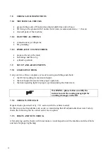


Electrical system
a check of the electrical system to verify that
control desk motor, limit switches and control
panel operate properly must be carried out by
skilled electricians
10 CHAPTER 10 - TROUBLESHOOTING
A list of possible troubles and solutions is given below
T
ROUBLE
:
P
OSSIBLE
C
AUSE
:
S
OLUTION
:
The lift does not work
The main switch is not turned
on
Turn the switch on
There is no power
Check Power on to restore if
necessary
The electrical wires are
disconnected
Replace
Fuses are blown
Replace
Printed circuit board does not
operate properly
Replace the printed circuit
board
The lift does not raise
The motor direction of rotation
is not correct.
Interchange the two phases on
the main switch
The oil in the hydraulic unit is
not sufficient.
Add some hydraulic oil
The UP button is faulty.
Check UP button and
connection for proper
operation. Replace, if needed
The lowering valve does not
close.
Check and clean, if dirty, or
replace, if faulty
The suction pump filter is
dirty.
Check and clean if needed.
The pump is faulty
Check the pump and replace, if
needed.
The lifting capacity is not
sufficient
Oil leakages in hydraulic
circuit
Check the circuit for any
leakage
Exceeding oil into hydraulic
circuit
Push lowering button and
discharging button
simultaneously
The lift does not lower when
the DOWN button is pressed (
without load)
The lowering solenoid valve
does not work properly
Verify if it is powered and
check magneto for damage
(replace if disconnected or
blown).
The lift does not lower when
the DOWN button is pressed
Locking solenoid valve is
jammed
Verify if it is powered and
check magneto for damage
(replace if disconnected or
blown)
The DOWN button is faulty
Replace the DOWN button
Printed circuit board does not
operate properly
Replace the printed circuit
board
73
Summary of Contents for 300 SPECIAL
Page 14: ...Figura 4 LAYOUT PSS MONOFORBICE WITH ESTENSION 51 ...
Page 15: ...Figura 4a LAYOUT PSS MONOFORBICE WITH FLAP 52 ...
Page 16: ...Figura 4b LAYOUT PSS MONOFORBICE ESTENSION WITH FRAME 53 ...
Page 17: ...Figura 4c LAYOUT PSS MONOFORBICE FLAP WITH FRAME 54 ...
Page 21: ...Figure 7 ELECTRICAL DIAGRAM 58 ...
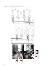
Page 29: ...Figure 16 HIDRAULIC HOSE CONECTION 66 A B F C ...


