


3-55
•
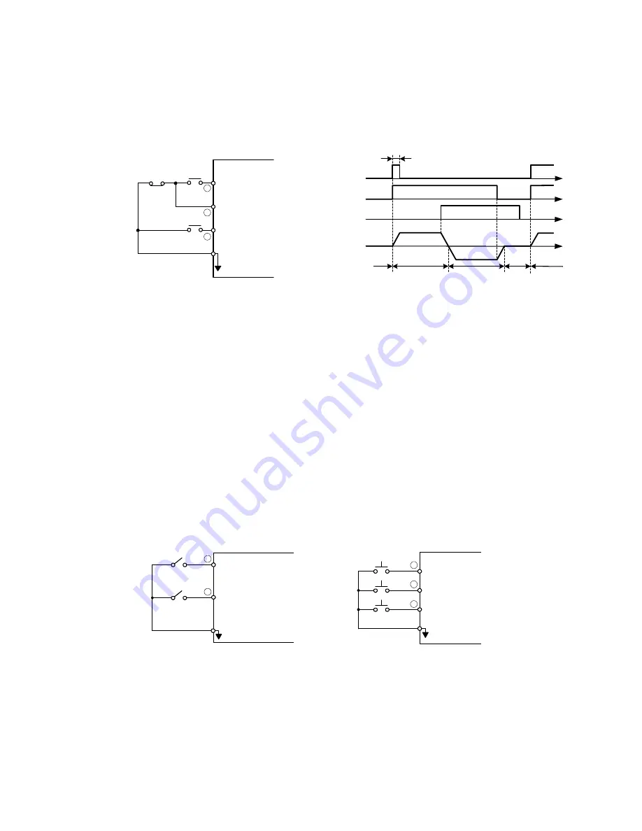
Forward/Reverse Change
(setting : 00)
•
Under 3-wire initialization mode (Sn-03= 8 or 10 or 12)
,
the multi-function
input terminals
g
~
j
have setting “00”, the inverter will be in the 3-wire mode
operation. As shown in
Fig. 37
, the Forward/Reverse change mode is set at the
terminal
g
.
Run Command
(ON : run)
SC
Run
(A contact)
1
2
5
Stop
(B contact)
Stop Command
(OFF : stop)
FWD/REV Cmd.
(multi-func.
input terminal)
RUN cmd.
STOP cmd.
FWD/REV
cmd.
ON or OFF
OFF
(stop)
OFF (FWD) ON (REV)
STOP
FWD
REV
> 50 ms
Motor
Speed
FWD
STOP
Fig. 37.
3-wire mode connection
diagram
Fig. 38.
Operation sequence in 3-wire mode
•
Input STOP Command during 2-Wire Mode Operation (setting : 01)
•
Under a standard 2-wire initialization mode as shown in Fig.
39(a)
, S1 and S2 can
not be both “ON” at the same time.
When S1= “ON” and S2= “OFF”, the motor is FWD running. When S1=”OFF” and
S2= “ON”, the motor is REV running. When S1= “OFF” and S2= “OFF”, the motor
stops running.
•
When Sn-25= ‘01’, the 2-wire operation mode has its self-sustaining function.
Only through the multi-function input terminal
g
, the operator can stop the
inverter after pressing the “STOP” key as shown in Fig.
39(b)
. As shown in Fig.
39(b)
, the switches S1, S2 and S3 do not need to be the self-sustaining switches.
When S1 is depressed “ON”, the motor will be forward running. After S3 is
depressed “ON”, the motor will stop. When S2 is depressed “ON”, the motor will
be reverse running. After S3 is depressed “ON”, the motor will stop.
FWD_RUN/STOP
SC
2
1
S1
OFF
ON
REV_RUN/STOP
S2
OFF
ON
(a)
FWD_RUN
SC
RWD_RUN
STOP
S1
S2
S3
1
2
5
(b)
Fig. 39.
2-wire mode connection diagram
Note
: 1. For the other setting value (except “00”, “01”), the external operation mode is
defaulted as 2-wire mode and no self-sustaining function. (that is, the inverter
will stop when contact
c
and
d
are not close.)
。


