background image

23

Attention: Please cut off the power before dialing.

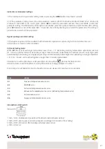
1. SW4-1 is switching the defrost mode. Default is “off”, it means traditional defrost by EA fan. When turn to “on”, the 

defrost mode is changed to be OA side heater defrost (required to connect the heater to the OA duct, only suggested 

in winter under –15°C), at this time the parameter 01 would be turned to 0 automatically and the supply air side 

electrical heater is not able to use.

Under electrical heater defrost mode, controller can automatic drive the electric heater on/off to heat

the fresh air in order to prevent frosting at the EA side of heat exchanger.

1) If the outdoor fresh air temperature < -15°C, the OA heater turns on for 50 minutes, then the ventilator switches 

off for 10 minutes and restarts.

2) If the OA heater switches on and the exhaust air temperature still <-1°C, then the ventilator will

stops for 50 minutes.

3) If the exhaust air temperature <-1°C and the outdoor air temperature >-15°C, the OA heater

switches on for 10 minutes for defrosting.

4) If the OA heater is on and temperature of outdoor air is >+25°C, then OA heater will stop for 5 minutes,

If the outdoor air temperature is detected over 25°C by sensor over 3 times, electrical heater stops.

2. SW4-2 is the by-pass mode. Default is “off”, it means that by-pass will open automatically based on the outdoor 

temperature. After connecting the bypass free voltage connector (refer to the wiring diagram), then bypass damper 

opens manually and fans run at high speed.

3. SW4-3 is switching the forced ventilation mode. Default is “off”, it means that ventilator is controlled by CO2 sensor. 

When turn to “on”, the ventilator is controlled by “humidity and temperature” sensor. CO2 sensor and “humidity and 

temperature” sensor is alternative, if SW4-3 turn to “ON” but without connecting “humidity and temperature” sensor, 

then E3 error happen.

4. SW4-4 is reserved.

External ON/OFF switch control logic

External switch can receive voltage free signal to control the ventilator on or off.

-Ventilator off, when ventilator have external on signal, ventilator run at high speed, when ventilator

have external off signal, ventilator return back to off.

- Ventilator on, when ventilator have external on signal, ventilator run at high speed, when ventilator have external 

off signal, ventilator return back to previous fan speed

Summary of Contents for HI-TECH PUR 12300012

Page 1: ...ax 39 0438 501516 Numero Verde 800 904474 only for Italy email info tecnosystemi com C F P IVA R I TV IT02535780247 Cap Soc 5 000 000 00 i v REV 07 08 08 2022 COD C20001060 Hi Tech Hi Tech HI TECH PUR...

Page 2: ...G Situations with a risk or death or serious injure Situazioni con rischio di lesioni o danni all apparecchio altri beni ATTENTION Situations with a risk of injury or equipment property damage I segue...

Page 3: ...L elettricista deve rispettare le norme nazionali e il manuale usando cavi specifici L uso di cavi con minore capacit e non correttamente installati pu comportare un rischio di folgorazione o incendi...

Page 4: ...outdoor ducts must be installed facing downwards to avoid rain water entering Improper installation can cause water leakage Installare un interruttore automatico di dimensioni idonee sull apparecchio...

Page 5: ...OLING 1 Vel 62 63 57 60 58 2 Vel 57 59 55 58 56 3 Vel 57 59 55 58 56 RISCALDAMENTO HEATING 1 Vel 65 67 63 64 62 2 Vel 61 61 57 62 59 3 Vel 61 61 57 62 59 EFF TERMICA TEMP EFF 1 Vel 73 76 74 76 76 2 Ve...

Page 6: ...15 111 270 144 HI TECH PUR 600 m3 h 904 824 107 754 960 19 500 111 270 194 HI TECH PUR 800 m3 h 884 1116 85 1045 940 19 428 170 388 242 HI TECH PUR 1000 m3 h 1134 1116 85 1045 1190 19 678 170 388 242...

Page 7: ...ng the unit and accessories during installation or whilst in storage on site Service ports should be installed to allow access for filter maintenance Tubo dell aria fresca esterno Outside Fresh Air Du...

Page 8: ...I INSTALLAZIONE PHYSICAL INSTALLATION Allaccio 1 Il punto di raccordo delle prese di aerazione e dei condotti dell apparecchio va sigillato o protetto con nastro isolante per impedire perdite d aria l...

Page 9: ...produce condensa o gelo con una curva di saturazione da A a C Usare un preriscaldatore per garantire il mantenimento di condizioni di curva idonee da B a B per passare da C a C per impedire la formazi...

Page 10: ...only when unit starts 10 Duct muffler may be considered if user wants indoor noise to be minimized Isolare la corrente durante l installazione e prima di un intervento di manutenzione per evitare lesi...

Page 11: ...seguite dall utente sull impianto elettrico e sui sistemi di controllo MODELLO MODEL CONDENSATORE CAPACITOR ALIMENTAZIONE ELETTRICA POWER SUPPLY MODELLO PANNELLO DI CONTROLLO CONTROL PANEL MODEL 12300...

Page 12: ...ND B AN2 AN1 AN3 AN4 COMM1S1 S2 C02 CN10 CN8 CN12 CN13 CN3 CN7 CN6 CN4 CN5 CN2 By pass switch External swith SA temp FR EA temp OA temp RA temp CO2 sensor Reserve switch RS485 ports Control panel Join...

Page 13: ...upply fan Voltage 220V 1ph 50 60Hz PE 0063 WIFI WIFI ports GM Yellow White Black By pass Control panel Joint of control panel and cable Standard length 5m Connect the tin end of cable to the port no s...

Page 14: ...a temperatura corrente di oA premendo il pulsante su gi e premere SET per salvare la modifica Contemporaneamente controllare se il bypass aperto o chiuso Non dimenticare di modificare la temperatura d...

Page 15: ...n an abnormal status may cause failure electric shock or fire Disattivare l alimentazione e l interruttore magne totermico mentre si pulisce lo scambiatore Switch off the power and breaker when you cl...

Page 16: ...ON Velocit dell ariadialimentazione Supplyairtemperature Temperatura dell aria di alimentazione Supplyairvelocity Corrente accesa Poweron Display ora Timedisplay Aria di alimentazione Supplyair Bypass...

Page 17: ...imo e secondo periodo di timer L utente pu scegliere il periodo premendo il pulsante MODE Se non si eseguono operazioni per 8 secondi il display si azzera e tutte le modifiche si annullano 7 Timer set...

Page 18: ...first or second period of timer User can choose the period of timer by pressing the button of MODE If no operation in 8 seconds display will disappear and all setting is invalid 7 Weekly timer off pr...

Page 19: ...Defrosting entering temperature 9 5 1 C Controllo principale Main control 06 Durata sbrinamento Defrosting duration time 2 20 10 Minuti Minutes Controllo principale Main control 07 Valore funzione sen...

Page 20: ...ura per 1 minuto e l intervallo di sbrinamento superiore a 30 minuti regolabile la ventola di scarico entra automaticamente in funzione ad alta velocit per lo sbrinamento e la ventola di alimentazione...

Page 21: ...djustable and last for 1 minute and the interval of defrosting is longer than 30 minutes adjustable the exhaust fan will run at high speed automatically for defrosting and supply fan will stop until E...

Page 22: ...a dell aria esterna rilevata dal sensore per 3 volte risulta superiore a 25C il riscaldatore elettrico si arresta 2 SW4 2 la modalit bypass Lo stato predefinito off significa che il bypass si apre aut...

Page 23: ...outdoor air is 25 C then OA heater will stop for 5 minutes If the outdoor air temperature is detected over 25 C by sensor over 3 times electrical heater stops 2 SW4 2 is the by pass mode Default is of...

Page 24: ...RNING Isolare la corrente prima dell installazione e di un intervento di manutenzione per evitare lesioni o folgorazioni I cavi di alimentazione l interruttore magnetotermico principale e la protezion...

Page 25: ...e del flusso d aria nelle prese di aerazione interne ed esterne diminuisce significativamente dopo un determinato periodo di funzionamento The airflow volumes both indoor and outdoor vents drop obviou...

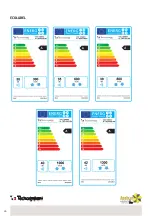
Page 26: ...26 ECOLABEL...

Page 27: ...di danni La garanzia non copre la sostituzione dei componenti che risultano danneggiati per trasporto non idoneo installazione non conforme a quanto specificato in questo manuale di installazione uso...

Page 28: ...28 NOTE NOTES...

Page 29: ...29 NOTE NOTES...

Page 30: ...30 NOTE NOTES...

Page 31: ...31 NOTE NOTES...

Page 32: ...i com via dell Industria 2 4 Z I San Giacomo di Veglia 31029 Vittorio Veneto Treviso Italia Tel 39 0438 500044 Fax 39 0438 501516 email info tecnosystemi com C F P IVA R I TV IT02535780247 Cap Soc 5 0...

Reviews: