background image

IST-2293.EO01.01/C


Istruzione / User’s Manual / Manuel d’utilisation 

Pag.9/9


TECNOCONTROL S.r.l. Via Miglioli 47 SEGRATE ( MI ) 

 Tel: 02/26 92 28 90   Fax: 02/21 33 734


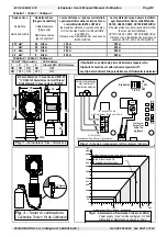
Tabella 1 / Table 1 / Tableau 1  

Sezione Cavo 


Cable Size 


Section des câble 

Resistenza Cavo 

[Singolo Conduttore] 


Cable Resistance 

[Single wire] 


Résistance câbles 

 [par Conducteur] 

La max distanza cui può essere installato 

ogni trasmettitore dalla centralina Tecno-

control Modello ID250 e SE148 è:  

the maximum distance to install each detec-

tor from the Gas Central Unit Model ID250 

and SE148 is:  

Distance max. d’installation des sondes avec 

ID250 et SE148 

La max distanza cui può essere installato 

ogni trasmettitore dalla centrali Modello 

CE100, CE400, CE600, CE700 (CE380UR) è: 

Tthe max distance to install each detector from 

the Gas Central Unit Model 

CE100, CE400, CE600, CE700 (CE380UR) is: 

Distance max. d’installation des sondes avec 

centrales CE 100, 400, 600, 700(CE380) 

0,75 mm

2

 26 

/km 

100 m  

300 m 

1 mm

2

 20 

/km 

150 m  

400 m 

1,5 mm

2

 14 

/km 

200 m  

500 m 

2,5 mm

2

 8 

/km 

400 m  

800 m 

Tabella 2 / Table 2 / Tableau 2


“S1-SET”(Dip-Switch)


LED Allarme


1


2


3


4


Alarm LED / LED d'alarme

ON


ON


ON


ON

 OFF 

ON


OFF


OFF


OFF


ON 

190

65 

83 

105 

70 

Ø42 

107 

Fig. 1 –


Dimensioni /

 Size / Dimensions 

Imbocco Femmina ¾” Gas Conico UNI 6125 

”¾” UNI 6125 Female Gas Conical Thread 

Entrée femelle ¾” Gaz Conique UNI 6125


12-

24

V


mA


1


2


3


4


ON


OFF


SET


+/- 

(12÷24Vdc)


Alimentazione / Power Supply / Alimentation


Centrale rivelazione gas 

Gas Central Unit 

Centrale de détection


RL

-


S


Dip Switch


+


Test Uscita 

Output Test 

Sortie Test 

40÷200mV


TP1   TP2


“S” - 

Uscita 4÷20 mA 

4÷20 mA Output / Sortie en 4÷20 mA


Fig. 2 -


Schema di collegamento / Wiring diagram / Schéma 

F2 

F1 

mV


0,3 L/min


Fig. 3 -

 Tester di calibrazione 

/ Calibration Tester / Kit de Calibration 


Alimentazione / Power Supply / Alimentation


100

300

400

500

50

0

5

200

Vdc

RL=Resistenza di carico / Load resistor / Resistance de charge

RL

Ohm

Fig.4 -


Alimentazione / Resistenza di Carico 4÷20mA 

Power supply / Load resistance diagram 4÷20mA 

Alimentation / Résistance de charge 4÷20mA


600

0

10

15


20


25

28

650

10,8

24

Area di funzionamento 
Allowable oparating region 

350

700

800


Il Dip-Switch va posizionato prima d’alimentare l’apparecchio. 

Dip-Switch should be set with instrument powered off. 
Les Dip-Switch doivent être paramétrés avant d'alimenter le détecteur
 

Summary of Contents for TS293EO

Page 1: ...ampo di misura Standard Range Champ de mesure 0 25 0 O2 Limite funzionamento Sensore Sensor limits Limite échelle 30 O2 Vita media in aria pulita Average Life in clean air Vie moyenne en air pur 2 anni years ans Tempo massimo di immagazzinamento Max Storage Time Temps maximum de stockage 3 mesi 3 month 3 mois Tempo di risposta Response Time Temps de réponse T90 30 secondi seconds secondes Ripetibi...

Page 2: ...are Ossigeno ma raggiunge le condizioni di stabilità ottimali dopo circa 15 minuti di funzionamento continuo Funzionamento Normale deve essere acceso il solo Led verde ON Il Led rosso ALARM si accende solo se è stato abilitato con il Dip Switch n 1 posizionato su ON se la concentrazione di gas O2 supera i 22 5 oppure scende sotto il 19 5 I Guasti sono indicati dall accensione del Led giallo FAULT ...

Page 3: ...F1 e F2 Per far sì che la pressione sul pulsante sia riconosciuta tenerlo premu to per circa un secondo finche non si spegne per un attimo il Led verde Dopodichè si può passare al pulsante successivo In caso d errore basta aspettare circa 10 secondi e la sequenza è automaticamente cancellata Kit di Taratura e Bombole con Miscela Gas per la Verifica la miscela da utilizzare è Gas Ossigeno al 15 vol...

Page 4: ...ut of scale or expired NOTES ON THE DETECTED GAS TS293EO has a sensor that can detect Oxygen O2 gas which is colourless odourless a little heavier than air its density as to air is 1 1 Oxygen is not a flammable gas it is a strong oxidant which reacts with reducing and fla mable materials increasing the risk of fire and explosion We all need to breathe the oxygen in air to live Air is made up of se...

Page 5: ...the CartridgeSensor Safety Oxygen sensors contain a small quantity potassium acetate solution which is corrosive Normally this ma terial would only leak out as a result of either mechanical damage or an incorrect instrument use beyond the limits of its operational functioning These sensors also contain small amounts of lead lead oxide platinum silver car bon and antimony If the user comes into con...

Page 6: ...air condition 20 9 v v Then opplying the 16 v v O2 gas insert the TC011 over the sensor holder adjust the sample gas cylinder valve as the flow meter indicates around 0 3 l mins see fig 3 wait for 1 2 minutes verify to read a value of about 143 mV corresponding to 14 3 mA 0 2 output and the Central Unit which is connected to the detector displays about 16 0 2 Then close the gas cylinder and remove...

Page 7: ...de la Cartouche il sera nécessaire d envoyer le détecteur au fournisseur pour réparation INSTALLATION Les détecteurs doivent être installés positionnés et vérifiés en suivant toutes les règles nationales en vigueur pour les installations électriques dans les zones avec dangers d explosions et les normes de sûreté des installations Montage en fig 1 sont indiquées les dimensions Le détecteur doit êt...

Page 8: ... être exécuté en air propre exclusivement milieu sans la présence de gaz toxiques ou autres A l aide des touches exécuter le Code d Etalonnage Attendre que les leds jaune et verte s allument et que la led rouge cli gnote la led rouge reste ensuite en feu fixe pour indiquer que la procédure est en fonction Attendre 3 minutes environ que la led rouge s éteigne au moins durant 2 secondes A ce point d...

Page 9: ...able 2 Tableau 2 S1 SET Dip Switch LED Allarme 1 2 3 4 Alarm LED LED d alarme ON ON ON ON OFF ON OFF OFF OFF ON 190 65 83 105 70 Ø42 107 Fig 1 Dimensioni Size Dimensions Imbocco Femmina Gas Conico UNI 6125 UNI 6125 Female Gas Conical Thread Entrée femelle Gaz Conique UNI 6125 S 12 24V mA 1 2 3 4 ON OFF SET 12 24Vdc Alimentazione Power Supply Alimentation Centrale rivelazione gas Gas Central Unit C...

Reviews: