background image

4.3 

Operating OSD Menu 

  In the live view screen interface, right-click within the live view window of the camera 

Step 1

that you want to configure. 

The shortcut menu (Figure 4-1) is displayed. 

  Click 

PTZ

Step 2

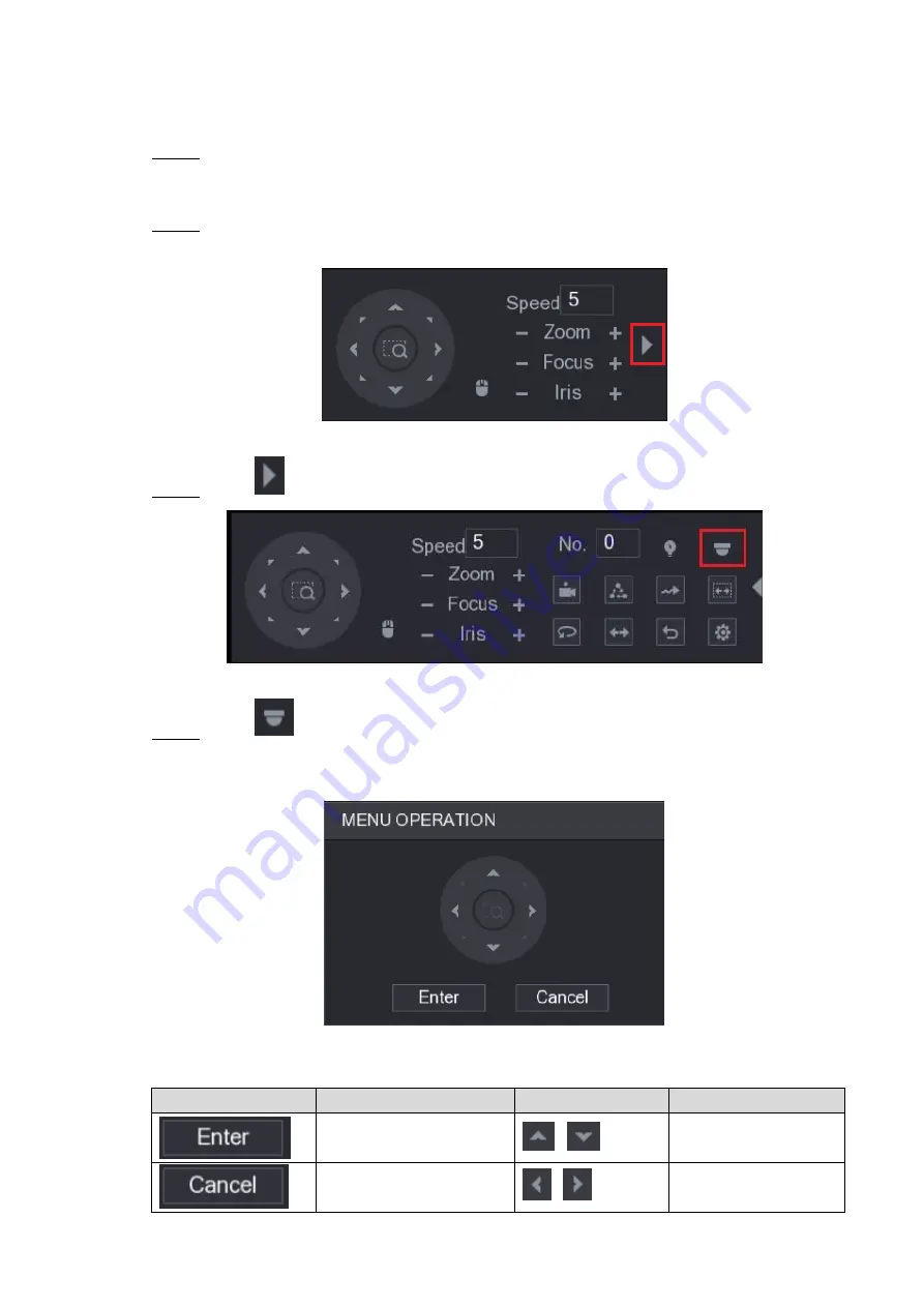
The PTZ setting interface is displayed. See Figure 4-5. 


Figure 4-5

  Click 

to see more options. See Figure 4-6. 

Step 3


Figure 4-6

  Click 

Step 4

The 

MENU OPERATION

 panel is displayed. See Figure 4-7. 

The OSD menu of the corresponding camera is displayed on the live view screen. 


Figure 4-7

For the function of the buttons in the MENU OPERATION panel, see Table 4-1. 

Button 

Function 

Button 

Function 

Enter or confirm an item 

Select item 

Exit OSD menu 

Change item value 

Summary of Contents for HDE5P2W2-A

Page 1: ...HDE5P2W2 S A 5MP 4 in 1 Dome Securityt Camera...

Page 2: ...d to be in compliance with the local privacy protection laws and regulations to protect the legitimate rights and interests of other people by implementing measures include but not limited to providin...

Page 3: ...ure if the camera power adapter meets the camera operating voltage requirement before powering up the device The material and length of the power cable might influence the device voltage Prevent the p...

Page 4: ...of PoC power supply do not connect any other device between the camera and PoC transceiver including UTC Balun optical transceiver distributor and convertor and so on otherwise the device might get b...

Page 5: ...he signal They are applicable to cover the high definition monitoring needs for locations like financial center telecom site supermarket hotel government school and factory 1 2 Features 720p series su...

Page 6: ...ormation about cable ports see Table 2 1 for the operation method of DIP switch see Table 2 2 No Port Name Function DC 12V Power Input Inputs DC 12V power Please be sure to supply power as instructed...

Page 7: ...s DC12V 2W power DIP Switch Dial switches to change output mode Switch up indicates ON switch down indicates OFF Table 2 1 Switch1 Switch2 Output Mode OFF OFF CVI ON ON CVBS ON OFF AHD OFF ON TVI Tabl...

Page 8: ...tal according to cable outlet requirement top out or side out then pull the cable out through mounting surface or the side cable tray Align the screw holes on the pedestal to those on the mounting sur...

Page 9: ...th coaxial cable then the live view screen is displayed The following instructions will guide you to configure your camera The number of the coaxial port on XVR will display at the lower left corner o...

Page 10: ...s menu until you goes back to the live view screen interface 4 2 Setting Audio Input Audio signal acquisition is available on select models In the Main Menu interface Figure 4 2 select CAMERA ENCODE E...

Page 11: ...ting interface is displayed See Figure 4 4 Figure 4 4 In the More Setting interface you can configure the audio settings Step 4 Enable Audio Encode function In the Audio Format list leave to the defau...

Page 12: ...is displayed See Figure 4 5 Figure 4 5 Click to see more options See Figure 4 6 Step 3 Figure 4 6 Click Step 4 The MENU OPERATION panel is displayed See Figure 4 7 The OSD menu of the corresponding c...

Page 13: ...after sale service for desiccant replacement if there is condensed fog found on the lens after unpacking or when the desiccant turns green Not all models are included with the desiccant Maintaining L...

Reviews: