


239
In section 2, left click the channel name you want to view, you can see the corresponding video in current
window.
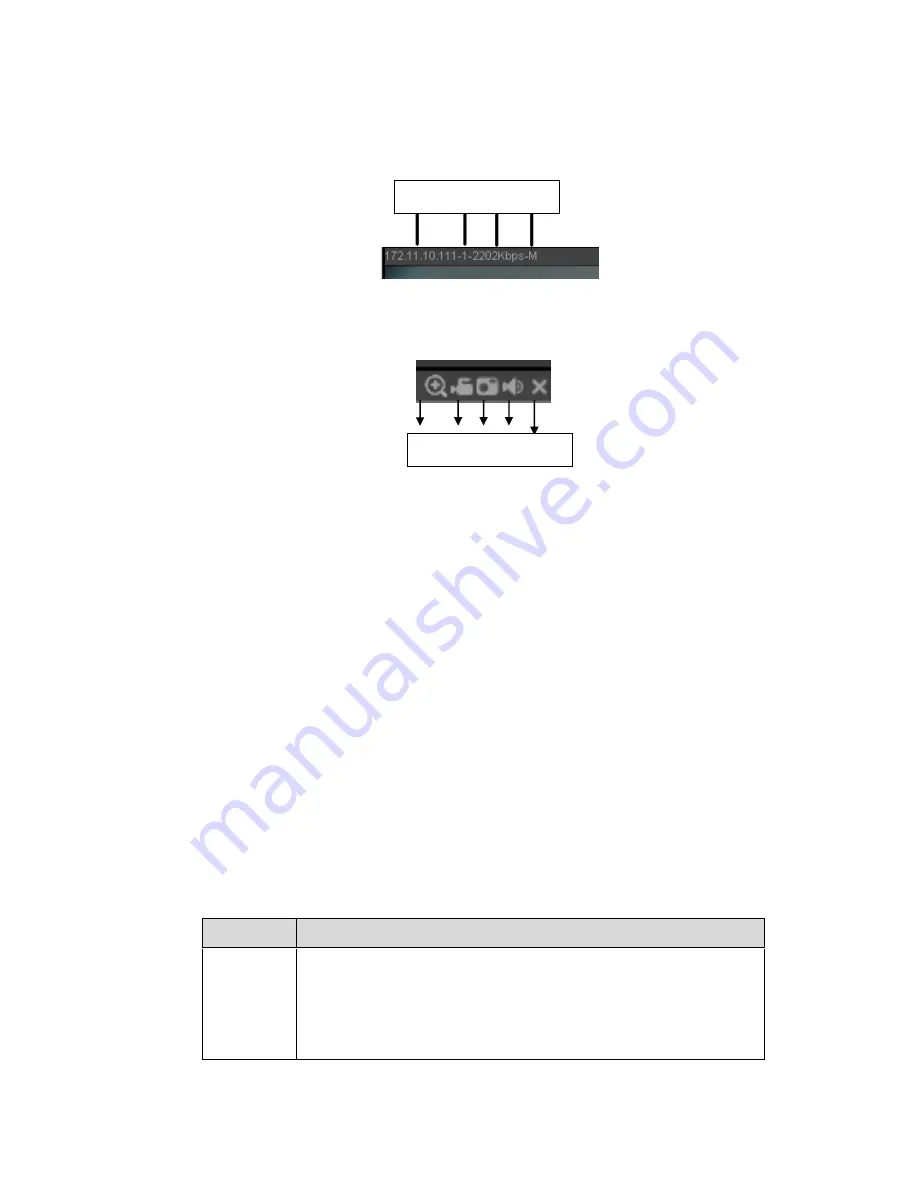
On the top left corner, you can view device IP(172.11.10.11), channel number(1), network monitor bit
stream(2202Kbps) and stream type(M=main stream, S=sub stream). See Figure 5-10.
Figure 5-10
On the top right corner, there are six unction buttons. See Figure 5-11.
Figure 5-11
1: Digital zoom: Click this button and then left drag the mouse in the zone to zoom in. right click
mouse system restores original status.
2: Local record. When you click local record button, the system begins recording and this button
becomes highlighted. You can go to system folder RecordDownload to view the recorded file.
3: Snapshot picture. You can snapshot important video. All images are memorized in system client
folder PictureDownload (default).
4: Audio :Turn on or off audio.(It has no relationship with system audio setup )
5: Close video.
5.4 PTZ
Before PTZ operation, please make sure you have properly set PTZ protocol. (Please refer to chapter
5.8.5.10).
There are eight direction keys. In the middle of the eight direction keys, there is a 3D intelligent
positioning key.
Click 3D intelligent positioning key, system goes back to the single screen mode. Drag the mouse in the
screen to adjust section size. It can realize PTZ automatically.
Please refer to the following sheet for PTZ setup information.
Parameter Function
Scan
Select Scan from the dropdown list.
Click Set button, you can set scan left and right limit.
Use direction buttons to move the camera to you desired location
and then click left limit button. Then move the camera again and
then click right limit button to set a right limit.
1 2 3 4 5
1 2 3 4
Summary of Contents for NVR-ELE8M-4K
Page 16: ...2 Front Panel and Rear Panel 2 1 Front Panel 2 1 1 The front panel is shown as in Figure...
Page 28: ...100 3 5 6 Please refer to Figure 3 6 for connection sample Figure 3 6...
Page 87: ...172 Figure 4 81 Figure 4 82...
Page 88: ...173 Figure 4 83 Figure 4 84...
Page 94: ...179 Figure 4 89 Figure 4 90...
Page 95: ...180 Figure 4 91 Figure 4 92...
Page 96: ...181 Figure 4 93 Figure 4 94...
Page 98: ...183 Figure 4 96 Figure 4 97...
Page 185: ...270 The motion detect interface is shown as in Figure 5 54 Figure 5 54 Figure 5 55...
Page 186: ...271 Figure 5 56 Figure 5 57 Figure 5 58...
Page 190: ...275 Figure 5 62 Figure 5 63...


