RUNRACE : Service & Maintenance Manual - rev. 2.0
Page 7.5
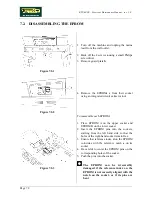
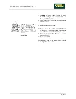
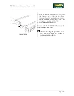
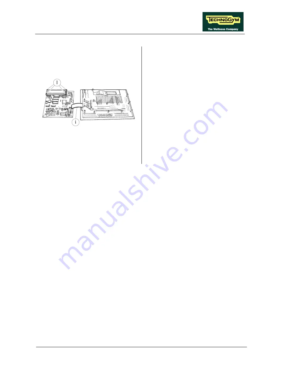
Figure 7.4-4
7. Separate the CPU board
g
from the LED
board
h
, turning it over toward the left and
being careful with strip
i
.
8. Using your hands, disconnect strip
i
from the
CPU board side.
9. Remove the circuit boards.
10. To disconnect the LCD from the CPU board,
back off the 4 screws
l
using a small Philips
screwdriver or release the 4 spring fasteners.
11. Disconnect or unsolder the cables on the
CPU board side.
12. Remove the LCD.
To reassemble the circuit boards, carry out the
above steps in reverse order.
Summary of Contents for Runrace
Page 1: ...SERVICE MAINTENANCE MANUAL REV 2 0 ...
Page 2: ......
Page 4: ......
Page 28: ...RUNRACE Service Maintenance Manual rev 2 0 Page 2 18 Page intentionally left blank ...
Page 144: ...RUNRACE Service Maintenance Manual rev 2 0 Page 8 12 Page intentionally left blank ...
Page 160: ...RUNRACE Service Maintenance Manual rev 2 0 Page 9 16 Page intentionally left blank ...
Page 182: ...RUNRACE Service Maintenance Manual rev 2 0 Page 11 16 Page intentionally left blank ...
Page 183: ......

