7
02/02/2012
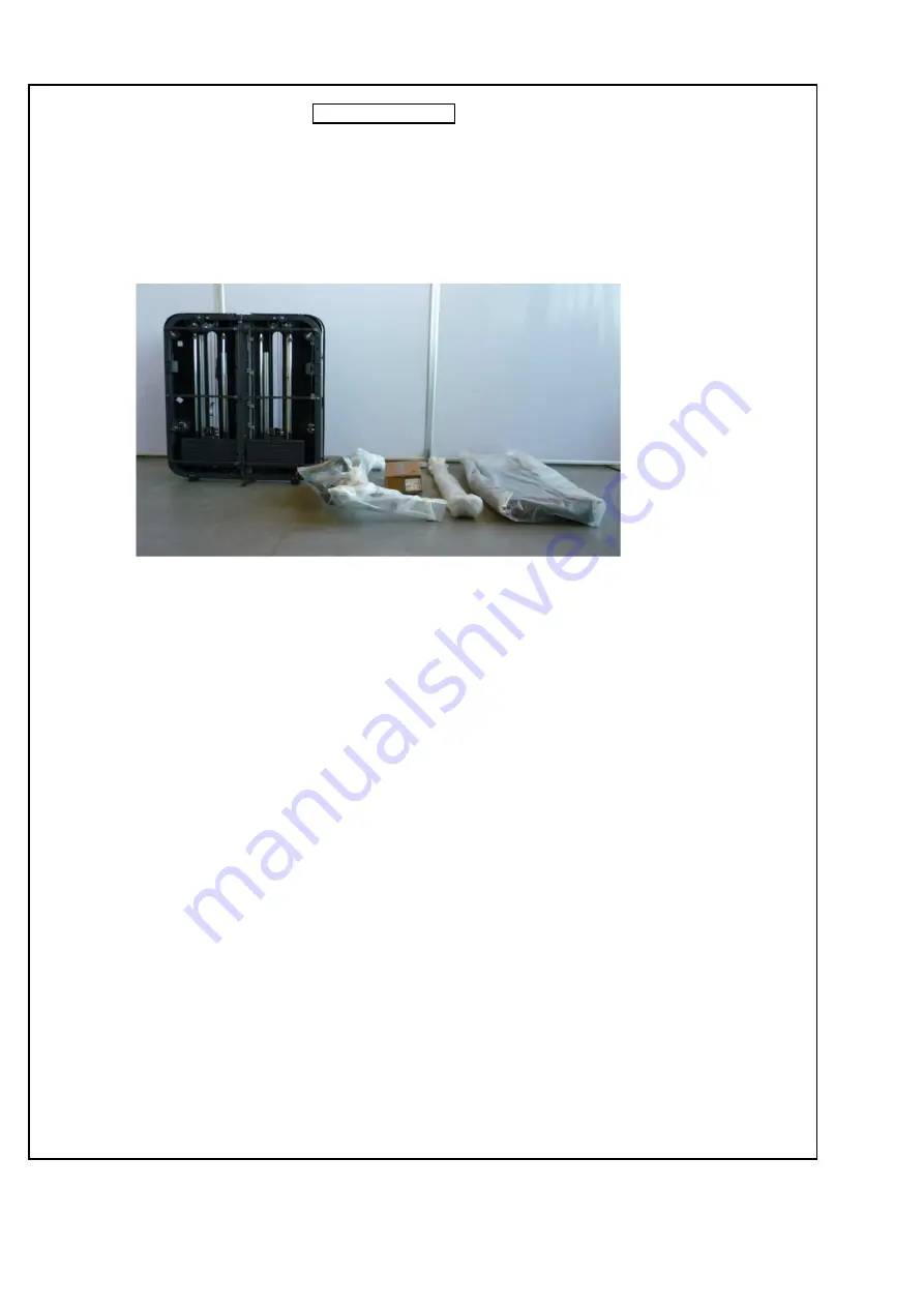
Transport the machine to the assembly zone using the hand truck or platform trolley depending on the type of
zone + the components
phase 5
Operator A/B
drafted by Fabrizio Frattiniapproved by Andrea Borghesi
revision 1/1
Page 1: ...MANUAL FOR KINESIS STATIONS STEP MH67E EQUIPMENT REQUIRED FOR INSTALLATION Combination ratcheting wrench 17 and or open end wrench 17 Scissors Electric screwdriver with Phillips head and or Phillips...
Page 2: ...M5x10 screw M10 self locking M8x16 screw H 0N001389 plate M10x85 screw Description General information HARDWARE Blister letter code A 0Z050 fixing time 5 2 50 Installation time minutes in std conditi...
Page 3: ...2 2012 Remove the cardboard packaging box MACHINE UNPACKING DO NOT USE A CUTTER MACHINE UNPACKING SEQUENCE phase 1 Operator A Operator B drafted by Fabrizio Frattini approved by Andrea Borghesi revisi...
Page 4: ...e black broken line Extract the machine components and place them near the unpacking zone Operator A Operator B phase 2 Remove 2 2 screws of the RH LH wooden crossbeams see detail drafted by Fabrizio...
Page 5: ...the wooden frame do not cut the 4 upper cable ties position the hand truck separate the wooden frame from the pallet and transport the machine to the area near the unpacking zone Operator A N O draft...
Page 6: ...6 02 02 2012 Remove wooden frame A and remove the polyethylene packet phase 4 Operator A B drafted by Fabrizio Frattini approved by Andrea Borghesi revision 1 1...
Page 7: ...nsport the machine to the assembly zone using the hand truck or platform trolley depending on the type of zone the components phase 5 Operator A B drafted by Fabrizio Frattini approved by Andrea Borgh...
Page 8: ...AND SEAT ASSEMBLY phase 1 Insert the rear foot in the frame assembly tighten with 2 screws K 1 screw J 2 2 washers nut F1 position and tighten the piston unit plate with 2 screws F2 MACHINE ASSEMBLY S...
Page 9: ...he 4 screws leaving them inserted of the pivoting unit box remove the cover phase 2 Remove the lower guard of the pivoting unit by loosening the internal screw Remove the front pivoting unit by leveri...
Page 10: ...r B phase 3 feed the cables through starting from the cable coming out of the RH pulley Operator A Repeat the same sequence of operations as operator A drafted by Fabrizio Frattini approved by Andrea...
Page 11: ...11 02 02 2012 phase 4 Operator A Operator B Repeat the same sequence of operations as operator A drafted by Fabrizio Frattini approved by Andrea Borghesi revision 1 1...
Page 12: ...e coming out of the RH central shaft Remove the pivoting unit by levering on the side hook Remove the lower guard of the pivoting unit by loosening the internal screw Repeat the same sequence of opera...
Page 13: ...Repeat the same sequence of operations as operator A Operator B Operator A phase 6 tighten the lower guard before inserting the pivoting unit drafted by Fabrizio Frattini approved by Andrea Borghesi...
Page 14: ...A Operator B Insert the ends of the RH cable in the appropriate housings of the RH handle the RH and LH handles are interchangeable to unscrew the barrel insert the L shaped key in the appropriate hol...
Page 15: ...ssembly in the appropriate housings and tighten with 2 screws M Insert 10 well nuts in the frame assembly Extract the platform position it in the frame assembly and tighten with 2 screws 2 washers pha...
Page 16: ...5 screws P 5 washers insert the RH handle Q ad tighten with 2 screws R Extract the LH guard and insert it in the frame assembly starting from the top and moving towards the bottom tighten with 5 screw...
Page 17: ...om bending Testing of the machine Delivery of the documentation and explanation of machine operation to the customer Cleaning of the assembly zone If the machine needs to be moved after it has been in...
Page 18: ...the following load bearing requirements guaranteed minimum load bearing capacity 50 kg ANCHORING THE MACHINE TO THE FLOOR In order to anchor the machine to the floor proceed in the same manner on both...