


8
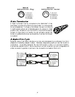
Data Terminator
A Data Terminator can be connected to the DMX-OUT of the
last fixture to reduce the effects of signal noise; it is not required
for all installations. To make a Terminator, connect a 120-ohm
¼ watt resistor across pin 2, Data Negative (S-) and pin 3, Data
positive (S+). Whether it is a 5 pin XLR or 3 pin XLR connector
(shown on right) does not matter, the pin numbers remain the
same. A qualified technician can determine if a Data Terminator
is needed.
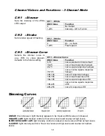
Adapter
5-to-3 pin
Systems using 5 pin DMX interfaces can be accommodated by purchasing 3-to-5 pin
adapters or building adapter cables. Numbers designating each pin can be found on
connectors. Converting between the two XLR types is done in a pin-to-pin fashion.
Connect the shields to pin 1, then connect pin 2 to pin 2 and pin 3 to pin 3, regardless of
either connector’s gender or pin count. No connection is made to Pins 4 & 5.
5 Pin XLR (Plug)
Pin 1: GND(Sheild)
Pin 2: Signal(-)
Pin 3: )
Pin 4: N/C
Pin 5: N/C
3 XLR
(S
)
Pin 1: GND(Sheild)
Pin 2: Signal(-)
Pin 3: )
Pin ocket
5 Pin XLR (Socket)
Pin 1: GND(Sheild)
Pin 2: Signal(-)
Pin 3: )
Pin 4: N/C
Pin 5: N/C
3
XLR
(Plug)
Pin 1: GND(Sheild)
Pin 2: Signal(-)
Pin 3: )
Pin
DMX-IN
1
2
3
4
5
- Ground
- Signal (-)
-
-
-
S
(Unused)
ignal
(+)
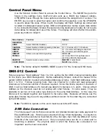
XLR Connector - Plug:
1
2
3
4
5
DMX-OUT
XLR Connector - Socket:
1
2
3
4
5
- Ground
- Signal (-)
-
-
-
S
(Unused)
ignal
(+)
1
2
3
4
5


