


7
Control Panel Menu
Use the fixture’s Control Panel to access the Control Menu. The MODE Key puts the
fixture in the settings menu itself and also acts as a BACK key between options,
UP/DOWN moves through the menu options and allows the assignment of a value. The
ENTER key is used to enter that option and confirms the selection once the UP/DOWN
is used to adjust the value. When in edit, the display will Flash. Settings are stored and
recalled on subsequent power cycles. DMX and master/slave modes require data cables
to be connected between fixtures. Manual and some stand-alone modes do not require
data cables for independent use of the fixture. The display will shut off after 30 seconds,
press any button to relight it.
Note:
The factory default CHANNEL MODE is set to “03” the 3 channel DMX mode.
DMX-512 Control
Fixtures require a "Start Address" from 1 to 512, setting the first DMX channel containing data
for the fixture (see DMX Background). Before addressing fixtures, consult the manual of the
system’s DMX controller to select a desirable addressing scheme. Valid Start Addresses range
from 1 to 512. Fixtures requiring more than one channel for control will read subsequent
channels up to the total number of channels required. Since this fixture requires 3 channels of
DMX, if set to a Start Address of 4 it would use data from channels: 4, 5, and 6. Choose a Start
Address so the channels used do not overlap with other fixtures. In some cases, it may be
desirable to set two or more same type fixtures to the same Start Address. In this case, the
fixtures will be slaved together and respond to the same data. Because all fixtures see the
same data, fixtures may be set to any address without concern for the order they are connected
by the DMX cables.
Note:
For DMX to operate on this unit it must be set to SLAVE mode.
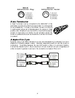
DMX Data Connection
This fixture uses 5 pin XLR type connectors and shielded twisted pair cable approved for
EIA-422/EIA485 use. Fixtures are connected in Daisy Chain topography: Connection is
made from the controller to the DMX-IN of the first light, then from the DMX-OUT to the
DMX-IN of the next light and so on. Only one data source can be on a chain and no
branching is allowed. The physical order in which the fixtures are connected is not
important, use the most convenient.
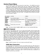
Menu Options
Function
Options
DMX MODE
ADDR
Select DMX Start Address
01-512
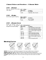
CHANNEL
Select Number of DMX Operating Channels 01 = 1 channel or 03 = 3 channels
DIMMER
CURVE
Selects dimming curve 1-8
01 – 04 curves with halogen response
05 – 08 curves with LED response
DIMMER
MANUAL
Allows a manual dimming setting
C:00 F:00
set C from 00-99 for brightness level
set F from 00-99 for flash speed
MASTER/
SLAVE MODE
Selects master or slave mode
MASTER
: master fixture
SLAVE
: slave fixture


