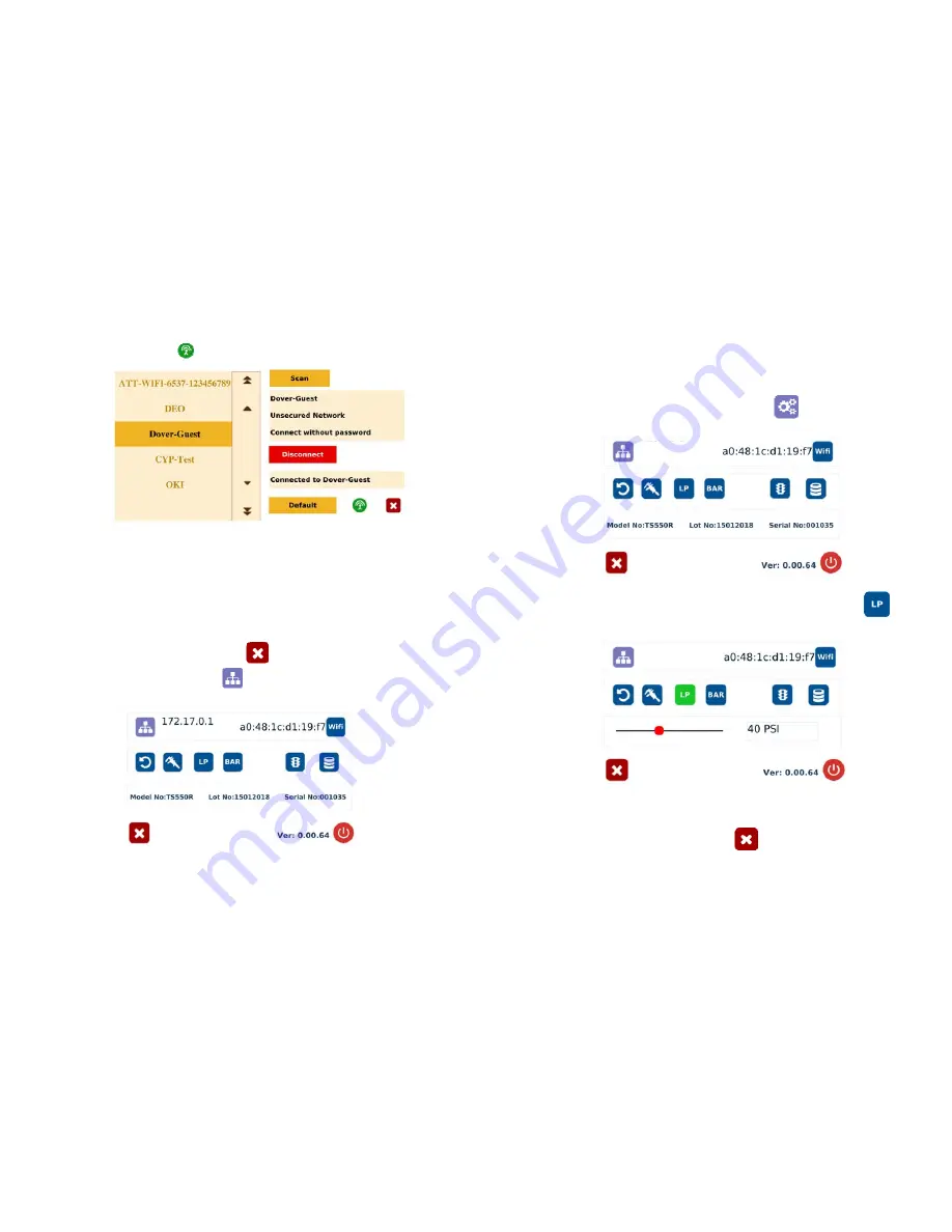
TECHCON SYSTEMS TS550R User Manual Download Page 13


20

6.


 If the selected network is an unsecured network (not password protected), 
touch “Connect” tab to connect 

7.


Once the unit is successfully connected to the Wi-Fi network, the 
“Connect” tab will change to “Disconnect” and the online symbol will 

change to green  


8.


If the selected network is a secured network (password protected), first 
create a text file and type the network’s password, then save the file as 
“password.txt” 

9.


Copy the “password.txt” file to a blank USB thumb drive.  

Note: Do not 

put the “password.txt” file inside a folder


10.


Insert the USB drive to the USB port located in the back of the unit 

11.


Touch “Connect” tab to connect.  Once the unit is successufully connected 
to the Wi-Fi network, remove the USB drive from the USB port 


12.


Touch X icon to save and exit   

13.


Touch the IP Address icon 

 and the unit will show an IP address


Note: Once the unit is turned off, the Wi-Fi connection is lost.  To re-connect 
the unit back to the same network after the unit is turned on, repeat steps 1-4 
and touch the “Default” tab. 


13


5.3


Low Pressure Alarm Setting 
Note: This controller is equipped with an adjustable “Low Pressure” alarm 
function.  If the set pressure dropped below the “Low Pressure” setting, the 
controller will not activate. The “Low Pressure” setting is pre-set at the factory 
to 70 psi (4.8 bars).  When the supplied pressure drops below 70 psi (4.8 bars) 
the unit will not function.  The “Low Pressure” setting can be adjusted. Follow 
the instructions below. 
 

1.


Touch the Setup icon to enter setup screen  


2.


Touch the Low Pressure (LP) icon to set the desired low pressure  


3.


Slide the pressure scale to set the desired low pressure threashold 


4.


Touch the X icon to save and exit 


Summary of Contents for TS550R

Page 1: ...TS550R SMART CONTROLLER FOR PNEUMATIC VALVES User Guide Copyright OK International...

Page 2: ...CYCLE FEEDBACK During a dispense cycle an open collector circuit closes and remains closed while the valve is dispensing Pin 3 and 4 can be as feedback signal to synchronize with other devices Power f...

Page 3: ...ith a Returns Authorization number prior to return Send warranty returns to Americas OK International 10800 Valley View Street Cypress CA 90630 1 714 230 2398 Europe OK International Eagle Close Chand...

Page 4: ...not actuate Supplied pressure dropped below Low Pressure setting Foot switch not plugged in or improperly plugged in Defective foot switch Broken wire or loose connection inside unit Defective solenoi...

Page 5: ...NA POWER SWITCH AIR INLET AIR OUTLET UNREGULATED FOOT SWITCH PORT POWER INLET IO PORT INTERNET PORT USB PORT GROUNDING TS560R 3 SPECIFICATIONS 4 FEATURES Figure 1 0 Size 290mm x 212mm x 98mm 11 4 X 8...

Page 6: ...d 3 Pressure Pot not included 4 Display 5 Power Adapter 6 Foot Switch 27 Proceed to make changes Click OK button to save The new parameters will be displayed on the controller 7 SOFTWARE UPGRADE Note...

Page 7: ...The controller parameters such as pressure and dispense time can be adjusted from the webserver Click on the Edit icon The parameter screen will appear as shown below 7 5 1 1 Login 1 Touch the Login...

Page 8: ...to 100 Note The digital values shown at 0 and 100 icons are for reference only The actual calibrated values will be different 9 Touch the Reboot icon to save the settings and reboot the system 10 Wai...

Page 9: ...Port A and Port B delivers the same output pressure This pressure is to activate the valve Make sure the supplied pressure is set at least 70 psi 4 8 bar 1 Touch the Pressure A B icon to enter the pr...

Page 10: ...uch the Timed mode icon to set the dispense cycle in pre set dispense time The icon should turn to green color 2 Touch the Dispense icon to enter the setup screen 3 Touch the Up and Down arrows to set...

Page 11: ...uld turn to green color 5 2 5 Teach Mode Setting In the teach mode the dispense time will be accumulated as long as the foot switch is depressed This is helpful in determining the required dispense ti...

Page 12: ...memory 1 continuously with 5000 ms delay between each activation 21 6 INTERNET of Thing IoT 6 1 Setup webserver on the computer 1 Go to Techcon Website www techconsystems com and download the followi...

Page 13: ...12 Touch X icon to save and exit 13 Touch the IP Address icon and the unit will show an IP address Note Once the unit is turned off the Wi Fi connection is lost To re connect the unit back to the sam...

Page 14: ...dispense parameters then touch the Save icon to save the data 5 4 2 To run in Single Sequence Mode 1 Touch the Run Method icon to enter sequence mode setup 19 5 7 To Connect to Wi Fi network 1 Connec...

Page 15: ...Mode icon 4 Touch the Check Mark icon to save 5 Touch the X icon to exit The screen will look similarly to the screen below Notes A If there is no delay time entered in the setting the operator has t...

Page 16: ...ms the controller will activate memory 1 to 3 continuously with 5000 ms delay between each activation 5 5 Cycle Counter The cycle counter records the numbers of automatic dispense cycle being activate...

Reviews: