background image

TECDrive TEC-3 User Guide Revision 1.20 


www.tecmotors.co.uk/tecdrive 

13


4

 
Pow

e

r &

 Co
n

trol
 W

iri

n

Shield Termination (Cable Screen) 

The safety ground terminal provides a grounding point for the motor cable shield. The motor cable shield connected to this terminal (drive end) 
should also be connected to the motor frame (motor end). Use a shield terminating or EMI clamp to connect the shield to the safety ground 
terminal. 

4.3.


Incoming Power Connection 

4.3.1.


Cable Selection 


For 1 phase supply, the mains power cables should be connected to L1/L, L2/N. 


For 3 phase supplies, the mains power cables should be connected to L1, L2, and L3.  Phase sequence is not important. 


For compliance with CE and C Tick EMC requirements, refer to section 4.10 EMC Compliant Installation on page 15. 


A fixed installation is required according to IEC61800-5-1 with a suitable disconnecting device installed between the TECDrive and the AC 
Power Source. The disconnecting device must conform to the local safety code / regulations (e.g. within Europe, EN60204-1, Safety of 
machinery).  


The cables should be dimensioned according to any local codes or regulations. Maximum dimensions are given in section 9.2. 

4.3.2.


Fuse / Circuit Breaker Selection 


Suitable fuses to provide wiring protection of the input power cable should be installed in the incoming supply line, according to the data in 
section 9.2 Rating Tables. The fuses must comply with any local codes or regulations in place.  In general, type gG (IEC 60269) or UL type J 
fuses are suitable; however in some cases type aR fuses may be required. The operating time of the fuses must be below 0.5 seconds. 


Where allowed by local regulations, suitably dimensioned type B MCB circuit breakers of equivalent rating may be utilised in place of fuses, 
providing that the clearing capacity is sufficient for the installation.  


The maximum permissible short circuit current at the TECDrive Power terminals as defined in IEC60439-1 is 100kA. 

4.3.3.


Optional Input Choke 


An optional Input Choke is recommended to be installed in the supply line for drives where any of the following conditions occur:- 

o


The incoming supply impedance is low or the fault level / short circuit current is high 

o


The supply is prone to dips or brown outs 

o


An imbalance exists on the supply (3 phase drives) 

o


The power supply to the drive is via a busbar and brush gear system (typically overhead Cranes). 


In all other installations, an input choke is recommended to ensure protection of the drive against power supply faults. Part numbers are 
shown in the table. 

Supply 

Frame Size 

AC Input Inductor 

230 Volt 

1 Phase 

OPT-2-L1016-20 

OPT-2-L1025-20 

N/A 

400 Volt 

3 Phase 

OPT-2-L3006-20 

OPT-2-L3010-20 

OPT-2-L3036-20 

OPT-2-L3050-20 

4.4.


Motor Connection 


The drive inherently produces fast switching of the output voltage (PWM) to the motor compared to the mains supply, for motors which 
have been wound for operation with a variable speed drive then there is no preventative measures required, however if the quality of 
insulation is unknown then the motor manufacturer should be consulted and preventative measures may be required. 


The motor should be connected to the TECDrive U, V, and W terminals using a suitable 3 or 4 core cable. Where a 3 core cable is utilised, 
with the shield operating as an earth conductor, the shield must have a cross sectional area at least equal to the phase conductors when 
they are made from the same material. Where a 4 core cable is utilised, the earth conductor must be of at least equal cross sectional area 
and manufactured from the same material as the phase conductors. 


The motor earth must be connected to one of the TECDrive earth terminals. 


Maximum permitted motor cable length for all models: 100 metres shielded, 150 metres unshielded. 

4.5.


Motor Terminal Box Connections 

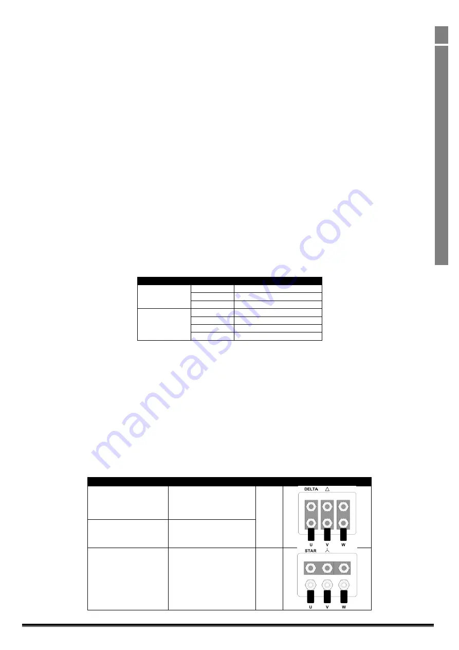
Most general purpose motors are wound for operation on dual voltage supplies. This is indicated on the nameplate of the motor. This 
operational voltage is normally selected when installing the motor by selecting either STAR or DELTA connection.  STAR always gives the higher 
of the two voltage ratings. 
 

Incoming Supply Voltage 

Motor Nameplate Voltages 

Connection 

230 

230 / 400 

Delta 


400 

400 / 690 

400 

230 / 400 

Star 


Summary of Contents for TECDrive TEC -3-120070-101 Series

Page 1: ...uide Revision 1 20 www tecmotors co uk tecdrive 1 1 Quick Start Up TECDrive User Guide IP20 IP66 NEMA 4X AC Variable Speed Drive 0 37 22kW 0 5 30HP 110 480V Distributed by TEC Electric Motors www tecm...

Page 2: ...TECDrive TEC 3 User Guide Revision 1 20 2 www tecmotors co uk tecdrive 1 Quick Start Up Di and Operating Instructions...

Page 3: ...ions 14 4 9 Motor Thermal overload Protection 15 4 10 EMC Compliant Installation 15 4 11 Optional Brake Resistor 15 5 Operation 16 5 1 Managing the Keypad 16 5 2 Operating Displays 16 5 3 Changing Par...

Page 4: ...g from transport receipt of delivery installation or commissioning The manufacturer also accepts no liability for damage or consequences resulting from inappropriate negligent or incorrect installatio...

Page 5: ...normally will be limited by the fuses or MCB Suitably rated fuses or MCB should be fitted in the mains supply to the drive according to any local legislation or codes Do not carry out any work on the...

Page 6: ...before connecting the supply 9 5 EMC Filter Disconnect 28 7 Check the supply cable and motor cable for faults or short circuits 8 Route the cables 9 Check that the intended motor is suitable for use...

Page 7: ...to Stop Connect a potentiometer 5k 10k between terminals 5 6 and 7 as shown o Adjust the potentiometer to vary the speed from P 02 0Hz default to P 01 50 60 Hz default Quick Start IP66 Switched Switc...

Page 8: ...1 0 75 1 4 3 1 TEC 3 120070 1F1 TEC 3 120070 101 1 5 2 7 1 TEC 3 220070 1F4 TEC 3 220070 104 1 5 2 7 2 TEC 3 220105 1F4 TEC 3 220105 104 2 2 3 10 5 2 N A TEC 3 320153 104 4 0 5 15 3 3 200 240V 10 3Pha...

Page 9: ...e suitable for use in pollution degree 1 environments according to IEC 664 1 For pollution degree 2 or higher environments drives should be mounted in a suitable control cabinet with sufficient ingres...

Page 10: ...section 9 1 The drive must be mounted vertically on a suitable flat surface The minimum mounting clearances as shown in the table below must be observed The mounting site and chosen mountings should b...

Page 11: ...nduit installations the conduit entry holes require standard opening to the required sizes specified per the NEC Not intended for installation using rigid conduit system Power Isolator Lock Off On the...

Page 12: ...d must be connected to system ground Ground impedance must conform to the requirements of national and local industrial safety regulations and or electrical codes The integrity of all ground connectio...

Page 13: ...mended to be installed in the supply line for drives where any of the following conditions occur o The incoming supply impedance is low or the fault level short circuit current is high o The supply is...

Page 14: ...STOP Run in Hand 0 4 Run in Hand Speed controlled from the Local POT Run in Auto 0 Speed controlled using Analog input 2 e g from PLC with 4 20mA signal Run in Speed Control STOP Run in PI Control 5 1...

Page 15: ...ry Supply Cable Type Motor Cable Type Control Cables Maximum Permissible Motor Cable Length C16 Shielded1 Shielded1 5 Shielded4 1M 5M7 C2 Shielded2 Shielded1 5 5M 25M7 C3 Unshielded3 Shielded2 25M 100...

Page 16: ...nds Press and hold the Navigate key 2 seconds To reset parameter values to their factory default settings press and hold Up Down and Stop buttons for 2 seconds The display will show Drive is enabled r...

Page 17: ...from the motor nameplate enables the slip compensation function and the TECDrive display will now show motor speed in RPM All speed related parameters such as Minimum and Maximum Speed Preset Speeds e...

Page 18: ...ncy 4 32 8 kHz Sets maximum effective switching frequency of the drive If rEd is displayed when the parameter is viewed the switching frequency has been reduced to the level in P00 32 due to excessive...

Page 19: ...Power On or Reset the drive will automatically start if Digital Input 1 is closed To Following a trip the drive will make up to 5 attempts to restart at 20 second intervals The numbers of restart att...

Page 20: ...mmunication An suffix means that the drive will coast stop output immediately disabled but will not trip P 37 Access Code Definition 0 9999 101 Defines the access code which must be entered in P 14 to...

Page 21: ...3 Advanced Parameters Par Description Minimum Maximum Default Units P 51 Motor Control Mode 0 5 0 0 Vector speed control mode 1 V f mode 2 PM motor vector speed control 3 BLDC motor vector speed contr...

Page 22: ...cess data output outgoing process data TX PDO1 for CANopen PO1 PO2 PO3 PO4 P00 23 Accumulated time with heatsink 85 C Hours Total accumulated hours and minutes of operation above heatsink temp of 85 C...

Page 23: ...T STOP P 24 When both inputs are active simultaneously the drive stops using Fast Stop Ramp Time P 24 E TRIP External Trip input which must be Normally Closed When the input opens the drive trips show...

Page 24: ...ntrol Mode P 12 3 4 7 8 or 9 P 15 DI1 DI2 DI3 AI2 DI4 AI1 Diagram 0 1 0 1 0 1 0 1 0 STOP ENABLE FB REF Fieldbus Speed Reference Modbus RTU CAN Master Slave defined by P 12 14 1 STOP ENABLE PI Speed Re...

Page 25: ...emperature U t Drive Under Temperature Th FLt Faulty Thermistor on Heat sink E trip External Trip 4 20 F 4 20mA fault Ph Ib Phase Imbalance P Loss Input Phase Loss Trip SC trp Communications Loss Trip...

Page 26: ...gh Run Enable Bit 1 Low Decel Ramp 1 P 04 High Decel Ramp 2 P 24 Bit 2 Low No Function High Fault Reset Bit 3 Low No Function High Coast Stop Request 2 R W Modbus Speed reference setpoint 0 5000 Setpo...

Page 27: ...8 15 3 25 200 240 10 V 3 Phase Input 3 Phase Output 1 0 37 0 5 3 4 6 6 8 8 2 3 1 0 75 1 5 6 10 10 8 8 4 3 1 1 5 2 9 5 16 15 8 8 7 2 1 5 2 8 9 16 15 8 8 7 100 2 2 2 3 12 1 16 17 5 8 8 10 5 50 3 4 5 20...

Page 28: ...cording to section 4 3 Suitable Power and motor cables should be selected according to the data shown in section 9 2 and the National Electrical Code or other applicable local codes Motor Cable 75 C C...

Page 29: ...sed over 10 C in order to start the drive 10 Factory Default parameters loaded 11 External trip E trip requested on digital input 3 Normally closed contact has opened for some reason If motor thermist...

Reviews: