


TECDrive TEC-3 User Guide Revision 1.20
www.tecmotors.co.uk/tecdrive
15
4
Pow
e
r &
Co
n
trol
W
iri
n
g
4.8.1.
Analog Output
The analog output function may be configured using parameter P-25, which is described in section 6.2 Extended Parameters on page 18.
The output has two operating modes, dependent on the parameter selection.
•
Analog Mode
o
The output is a 0
–
10 volt DC signal, 20mA max load current
•
Digital Mode
o
The output is 24 volt DC, 20mA max load current
4.8.2.
Relay Output
The relay output function may be configured using parameter P-18, which is described in section 6.2 Extended Parameters on page 18.
4.8.3.
Analog Inputs
Two analog inputs are available, which may also be used as Digital Inputs if required. The signal formats are selected by parameters as follows
•
Analog Input 1 Format Selection Parameter P-16
•
Analog Input 2 Format Selection Parameter P-47
These parameters are described more fully in section 6.2 Extended Parameters on page 18.
The function of the analog input, e.g. for speed reference or PID feedback for example is defined by parameters P-15. The function of these
parameters and available options is described in section 7 Analog and Digital Input Macro Configurations on page 23.
4.8.4.
Digital Inputs
Up to four digital inputs are available. The function of the inputs is defined by parameters P-12 and P-15, which are explained in section 7
Analog and Digital Input Macro Configurations on page 23.
4.9.
Motor Thermal overload Protection
4.9.1.
Internal Thermal Overload Protection
The drive has an in-
built motor thermal overload function; this is in the form of an “I.t
-
trP” trip after delivering >100% of the valu
e set in P-08
for a sustained period of time (e.g. 150% for 60 seconds).
4.9.2.
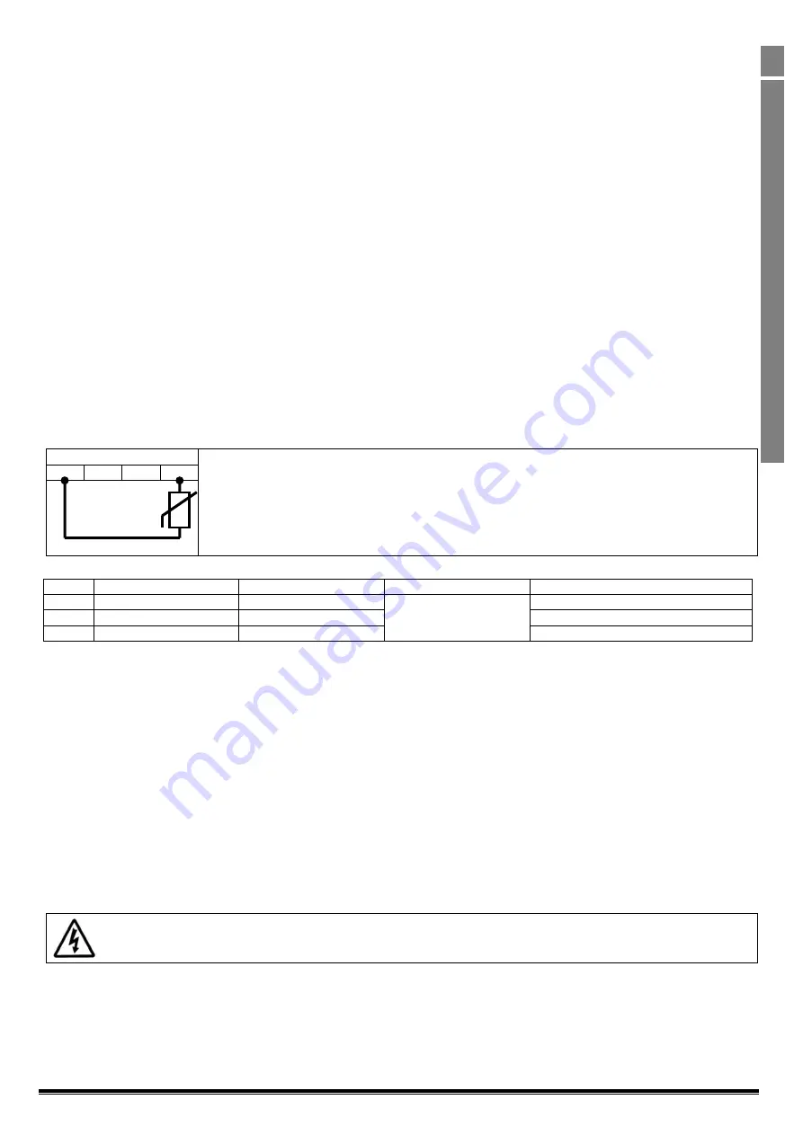
Motor Thermistor Connection
Where a motor thermistor is to be used, it should be connected as follows:-
Control Terminal Strip
Additional Information
•
Compatible Thermistor : PTC Type, 2.5k
Ω
trip level
•
Use a setting of P-15 that has Input 3 function as External Trip, e.g. P-15 = 3. Refer to section 7 for
further details.
•
Set P-
47 = “
"
1
2
3
4
4.10.
EMC Compliant Installation
Category
Supply Cable Type
Motor Cable Type
Control Cables
Maximum Permissible Motor Cable Length
C1
6
Shielded
1
Shielded
1,5
Shielded
4
1M / 5M
7
C2
Shielded
2
Shielded
1, 5
5M / 25M
7
C3
Unshielded
3
Shielded
2
25M / 100M
7
1/ A screened (shielded) cable suitable for fixed installation with the relevant mains voltage in use. Braided or twisted type screened cable
where the screen covers at least 85% of the cable surface area, designed with low impedance to HF signals. Installation of a standard cable
within a suitable steel or copper tube is also acceptable.
2/ A cable suitable for fixed installation with relevant mains voltage with a concentric protection wire. Installation of a standard cable within a
suitable steel or copper tube is also acceptable.
3/ A cable suitable for fixed installation with relevant mains voltage. A shielded type cable is not necessary.
4/ A shielded cable with low impedance shield. Twisted pair cable is recommended for analog signals.
5/ The cable screen should be terminated at the motor end using an EMC type gland allowing connection to the motor body through the largest
possible surface area. Where drives are mounted in a steel control panel enclosure, the cable screen may be terminated directly to the control
panel using a suitable EMC clamp or gland, as close to the drive as possible. For IP66 drives, connect the motor cable screen to the internal
ground clamp.
6/ Compliance with category C1 conducted emissions only is achieved. For compliance with category C1 radiated emissions, additional
measures may be required, contact your Sales Partner for further assistance.
7/ Permissible cable length with additional external EMC filter
4.11.
Optional Brake Resistor
TECDrive E3 Frame Size 2 and above units have a built in Brake Transistor. This allows an external resistor to be connected to the drive to
provide improved braking torque in applications that require this.
The brake resistor should be connected to the “+” and “BR” terminals as shown.
The voltage level at these terminals may exceed 800VDC
Stored charge may be present after disconnecting the mains power
Allow a minimum of 5 minutes discharge after power off before attempting any connection to these terminals
Suitable resistors and guidance on selection can be obtained from your Invertek Sales Partner.


