background image

(i)

Safety Summary

EM1-33039E

Safety Summary

Personal safety in handling or maintaining the equipment is extremely important.  Warnings and Cautions
necessary for safe handling are included in this manual.  All warnings and cautions contained in this
manual should be read and understood before handling or maintaining the equipment.
Do not attempt to effect repairs or modifications to this equipment.  If a fault occurs that cannot be rectified
using the procedures described in this manual, turn off the power, unplug the machine, then contact your
authorized TOSHIBA TEC representative for assistance.

Meanings of Each Symbol

This symbol indicates warning items (including cautions).
Specific warning contents are drawn inside the     symbol.
(The symbol on the left indicates a general caution.)

This symbol indicates prohibited actions (prohibited items).
Specific prohibited contents are drawn inside or near the     symbol.
(The symbol on the left indicates “no disassembling”.)

This symbol indicates actions which must be performed.
Specific instructions are drawn inside or near the    symbol.
(The symbol on the left indicates “disconnect the power cord plug from the outlet”.)

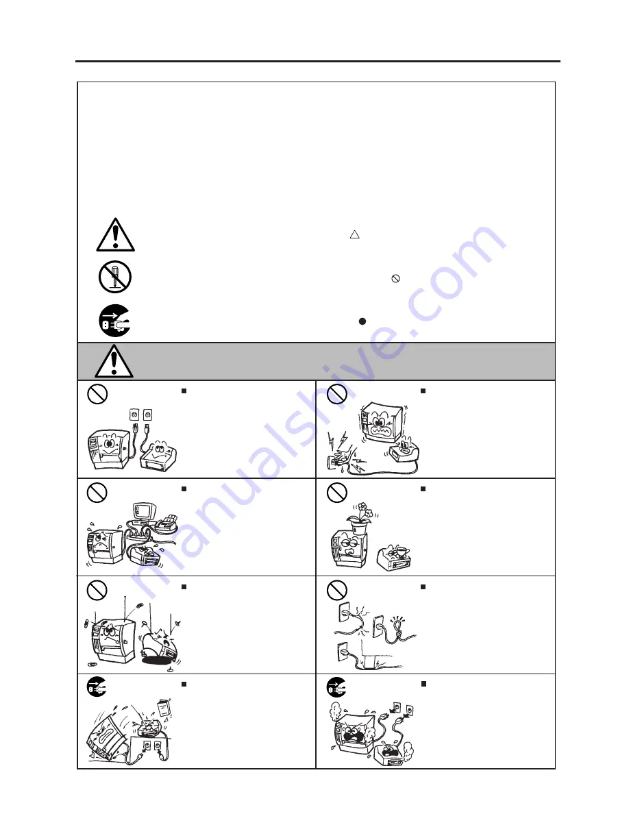
   Do not use voltages other than the
voltage (AC) specified on the rating
plate, as this may cause fire or
electric shock.

Any other than the
specified AC voltage
is prohibited.

WARNING

This indicates that there is the risk of death or serious injury if the
machines are improperly handled contrary to this indication.

Prohibited

   Do not plug in or unplug the power
cord plug with wet hands as this may
cause electric shock.

   Do not place metal objects or
water-filled containers such as flower
vases, flower pots or mugs, etc. on
top of the machines.  If metal objects
or spilled liquid enter the machines,
this may cause fire or electric
shock
.

   If the machines share the same
outlet with any other electrical
appliances which consume large
amounts of power, the voltage will
fluctuate widely each time these
appliances operate.  Be sure to
provide an exclusive outlet for the
machine as this may cause the
machines to malfunction.

   Do not insert or drop metal,
flammable or other foreign objects into
the machines through the ventilation
slits, as this may cause fire or electric
shock
.

Prohibited

Prohibited

Prohibited

   Do not scratch, damage or modify
the power cords.  Also, do not place
heavy objects on, pull on, or exces-
sively bend the cords, as this may
cause fire or electrical shock.

Prohibited

   Continued use of the machines in an
abnormal condition such as when the
machines are producing smoke or
strange smells may cause fire or elec-
tric shock
.  In these cases, immedi-
ately turn off the power switches and
disconnect the power cord plugs from
the outlet.  Then, contact your author-
ized TOSHIBA TEC representative for
assistance.

Disconnect
the plug.

   If the machines are dropped or their
cabinets damaged, first turn off the
power switches and disconnect the
power cord plugs from the outlet, and
then contact your authorized
TOSHIBA TEC representative for
assistance.  Continued use of the
machine in that condition may cause
fire or electric shock.

Disconnect
the plug.

Summary of Contents for TEC B-870 SERIES

Page 1: ...TEC Thermal Printer B 870 SERIES Owner s Manual...

Page 2: ...ssly approved by manufacturer for compliance could void the user s authority to operate the equipment WARNING This is a Class A product In a domestic environment this product may cause radio interfere...

Page 3: ...s indication Prohibited Do not plug in or unplug the power cord plug with wet hands as this may cause electric shock Do not place metal objects or water filled containers such as flower vases flower p...

Page 4: ...ribbons DO NOT STORE the paper or ribbons where they might be exposed to direct sunlight high tem peratures high humidity dust or gas Ensure the printer is operated on a level surface Any data stored...

Page 5: ...6 1 7 LOADING THE RIBBON 7 1 8 LOADING THE MEDIA 8 1 9 INSERTING THE OPTIONAL FLASH MEMORY CARD 9 1 10 CARE HANDLING OF THE MEDIA AND RIBBON 10 1 11 GENERAL MAINTENANCE 11 1 11 1 CLEANING 11 1 11 2 U...

Page 6: ...yreduced graphic data transfer times and you have a printer to suit a variety of applications and environments Optional features include a strip mechanism and Cutter mechanism This manual contains gen...

Page 7: ...spectivemodules are fitted Message display 20 characters x 1 line Dimensions 437 mm width x 282 mm depth x 395 mm height Weight 25 kg without media and ribbon Available bar code types JAN8 JAN13 EAN8...

Page 8: ...y as follows Print speed Ribbon loss 3 sec Approx 5 mm 4 sec Approx 10 mm 8 sec Approx 23 mm 2 2 OPTION Description A stop and cut swing cutter This interface kit allows extremely high speed informati...

Page 9: ...17 10 0 213 3 25 0 993 0 5 5 320 0 20 9 320 0 23 0 320 0 5 5 661 3 20 9 661 3 23 0 661 3 8 0 320 0 23 4 320 0 23 4 320 0 8 0 661 3 23 4 661 3 23 4 661 3 2 5 20 0 2 5 20 0 6 0 20 0 Label 38 999 0 Tag...

Page 10: ...a communication error occurs when the media ribbon ends or the printer does not operate correctly FEED Key Feeds paper RESTART Key Resets the printer when paused or when an error occurs Used to set t...

Page 11: ...t the power off time ON OFF READY BUSY DTR No XON is output at the power on time No XOFF is output at the power off time OFF ON XON XOFF READY BUSY XON is output at the power on time XOFF is output at...

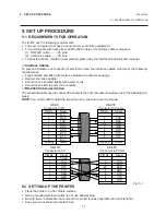
Page 12: ...le used to connect the printer to the host computer should be one of the following two types NOTE Use an RS 232C cable with imperial inch connector securing screws DB 9S Connector to PC DB 25P Connect...

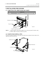
Page 13: ...e 2 Different cables cannot be used at the same time 6 2 HOLDER STAND INSTALLATION Fit the left and right side holders into the dowels of the holder base and fasten the side holders to the holder base...

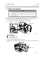
Page 14: ...rinter OPEN WARNING 1 Do not touch moving parts To reduce the risk that fingers jewelry clothing etc be drawn into the moving parts push the switch in the OFF position to stop movement 2 To avoid inju...

Page 15: ...the ribbon wrinkles while printing move the ribbon levers back or forth until the wrinkle is removed Protrusion Ribbon Core Notch Ribbon Ribbon Lever STEP 1 STEP 2 Spring Guide Wheel Guide Wheel Fig 7...

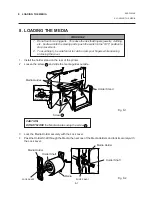
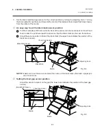
Page 16: ...dia Holder Holder Shaft Media Holder Holder Shaft Lock Lever Media Lock Lever Release Lock CAUTION DO NOT MOVE the Media Guides using the screw WARNING 1 Do not touch moving parts To reduce the risk t...

Page 17: ...e bushes of the Holder Shaft into notches of the Holder Stand securely 6 The black mark feed gap sensor is selectable between the fixed type and the movable type by changing the DIP switch Refer to pa...

Page 18: ...the media back on it s self and feed it under the print head past the sensor so that the black mark can be seen from above Adjust the sensor position to that of the black mark the upper hole indicates...

Page 19: ...d feed it through the cutter module NOTES 1 Be sure to cut the backing paper of label Cutting label will cause the glue to stick to the cutter which may affect the cutter quality and shorten the cutte...

Page 20: ...en the strip roller and the backing paper holder After taking up any slack of the media set the backing paper release bar in position Fig 8 8 Media Backing Paper Backing Paper Holder Backing Paper Rel...

Page 21: ...a damp place 5 Before inserting or removing the card make sure that the power switch is turned off 6 The following flash cards can be used The 1MB card is read only and the 4MB card can read write Fl...

Page 22: ...re high humidity dust or gas The thermal paper used for direct thermal printing must not have the specifications which exceed Na 800 ppm K 250 ppm and CL 500 ppm Some ink used on pre printed labels ma...

Page 23: ...l moistened cloth Print Head Platen Element Print Head Cleaner 24089500013 WARNING 1 Be sure to disconnect the power cord prior to performing any maintenance 2 Do not use any tool that may damage the...

Page 24: ...ibbonendsensorplate besuretofitbothstudsinthenotchesoftheribbon end sensor plate 9 Remove the pinch roller block then clean the roller belt and feed roller with cloth moistened by alcohol Fig 11 2 Stu...

Page 25: ...by wiping with a dry cloth or a cloth slightly dampened with a mild detergent solution NOTE Clean printer cover with an electrostatic free cleaner for automated office equipment Screw Media Guide Scr...

Page 26: ...media DO NOT USE any sharp implement or tool as these could damage the printer 7 Clean the print head and platen then remove any further dust or foreign substances 8 Place the portion of the media gui...

Page 27: ...Lower the backing paper release bar to remove the jammed media 2 Clean the strip roller and backing paper holder with ethyl alcohol White Screw Cutter Unit Swing Cutter Media Guide Screw Fixed Cutter...

Page 28: ...is displayed 7 Press the FEED key 8 Thereflectivesensor blackmarksensor isselected 9 Press the FEED key again 10 Thetransmissivesensor feedgapsensor isselected 11 Press and hold the PAUSE key 12 The m...

Page 29: ...PAUSE key for more than 3 seconds and it will begin to feed After it has fed 2 labels release or more the PAUSE key Press the RESTART key for ON LINE mode Threshold setting is now completed NOTES 1 I...

Page 30: ...edia path is jammed and does not feed smoothly 3 The installed media type does not match the selected sensor 4 The black mark position on the media does not match the sensor position 5 The installed m...

Page 31: ...y card and retry 3 Turn the power off and contact your Authorized Service representative Replace the card with a new one and re send data Only 1MB and 4 MB cards can be used Turn the power off then on...

Page 32: ...dia and the ribbon is loaded correctly 2 Check whether the print head is set correctly or not 3 Check the cabling between the printer and the host Dirty print head Clean the print head Call your Autho...

Page 33: ......

Page 34: ...PRINTED IN JAPAN EM1 33039E E...

Reviews: