


22
23
®
®
Periodically examine your Speed-T for the following:
•
Keep your vehicle clean using a brush to remove dirt
and dust.
•
Look for cracks in the suspension arms and other
molded parts.
•
Check that the tires are still glued to the wheels.
•
Check that all the wheel bearings are clean and lubricated.
•
Using your tools, attempt to tighten all the screws and
nuts.
•
Verify that the Chamber Links and Steering linkage are
not bent.
•
Check that the Toe and Chamber settings are as desired
and equal.
•
Remove the gear cover.
o Check the Spur gear for wear.
o Check the Pinion gear.
o Check the Slipper Pads for wear.
•
Take the shocks off the vehicle and check, especially if they
appear to be leaking as it is time to rebuild them.
•
Look over all the wiring and connections for bare wire or
any place which could lead to a short circuit.
•
Verify that the ESC and capacitor are securely mounted to
the chassis.
•
Verify the receiver is still securely mounted to the chassis.
•
Turn on the radio and if the Green LED is off or dim replace
the 4 AA batteries in the transmitter.
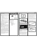
After you become familiar with driving your Speed-T,
you may need to reset or make adjustments for better
driving performance.
Just as in a real car, alignment is an important factor in your
vehicle’s handling. When you are ready to make adjustments
it is a good idea to have a flat work space to place your vehicle
on. This will enable you to easily and more quickly make both
Toe-in and Chamber adjustments. These adjustments should be
set with the vehicle sitting at its normal ride height.
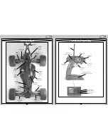
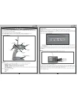
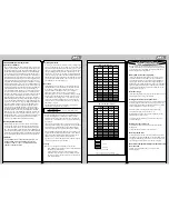
Tuning the Front End of the Speed-T
Shock Location
: The Speed-T has two mounting locations
on the front shock tower. The position can be easily adjusted
by simply moving the top of the shock to another hole. The
standard location (outside hole on the tower) works best on
most surfaces. Moving the top of the shock inward a hole will
slow steering response and make the Speed-T smoother in
bumps. The standard position on the arm is outside, which
offers the best balance. Running the inside shock location
will give the Speed-T more steering into the turn and less
steering on corner exit. Running the shock location outside on
the front arm will give you less overall steering into the turn
and keep the front end flatter through the turn, making the
Speed-T smoother and easier to drive. This can be used on high
traction surfaces. Keep in mind as you move the shocks in on
the arm this will require internal limiters to obtain the correct
suspension travel. For the inside location a total of .200" limiter
works great. Losi sells a shock spacer set (LOSA5050) that
includes .030", .060", .090" and .120" spacers.
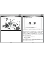
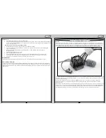
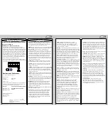
All of the Camber and Steering Linkages have been assembled
in the following way.
Using the supplied flat metal turn buckle wrench if you need to
SHORTEN any link on the Speed-T rotate the wrench towards
the front of the vehicle (counter-clockwise). If you need to
LENGTHEN any link then rotate the wrench towards the rear of
the vehicle (clockwise).
Static Camber
: This refers to the angle of the wheels/tires
relative to the surface (viewed from either the front or back).
Negative camber means that the top of the tire leans in toward
the chassis. Positive camber means the top of the tire leans out,
away from the chassis. Camber can be precisely measured with
after-market camber gauges, sold at a local hobby shop. It can
be measured (roughly) using any square (to the ground) object
by checking the gap between the square edge and the top of
the tire. Testing has shown that 1 degree of negative camber
is best for most track conditions. Increasing negative camber
(in the range of 1-2 degrees) will generally increase steering.
Decreasing negative camber (in the range of 0-1 degree) will
generally decrease steering and the Speed-T will feel easier to
drive as a result. This is, most often, a very critical adjustment in
tuning your Speed-T that can be made quickly and easily.
I
nboard Camber Location
: The Speed-T has three different
inner locations with vertical adjustment for the front camber
tie rod. In general, the lower or further out the inside position
is, relative to the outside, the more camber gain (total camber
change through the total throw of the suspension) is present.
This is an adjustment that is difficult to make a generic
statement for as it can have slightly different results on various
conditions. The following is a summary of how this adjustment
will usually impact the handling of the Speed-T. A longer front
camber link will usually make the Speed-T feel stiffer. This will
help keep the Speed-T flatter with less roll, but can make the
Speed-T handle worse in bumpy conditions, it also will make
the Speed-T easier to drive. A shorter front camber link will
result in more front end roll, which will provide more steering
on tighter turns with the loss of some stability. You will also lose
some high speed steering but might gain some more steering
response. Too short of a front link may make the Speed-T feel
“twitchy” or “wandery” meaning that it may be difficult to drive
straight at high speed.
Inboard Camber Vertical Adjustment
: Washers are often
used under the inner ball stud mounting location; this is
one of the most important adjustments on the Speed-T. You
should get a feel for how the number of washers affects the
handling. Adding washers will make the Speed-T more stable
and keep the front end flatter. This works well on higher
traction surfaces. Removing washers will make the steering
more aggressive, which works well on lower traction surfaces.
This can be good in some conditions, but can also make
the Speed-T difficult to drive in others. The best all-around
adjustment is with three washers as the vehicle comes built.
The washers that are used are included in an assortment
package of washers (LOSA6350).
Outboard Camber Location
: In addition to the inboard
camber location, the Speed-T also provides outboard three
mounting options. The middle location is the most used as it
provides the best and most consistent handling on different
surfaces. The outer location also helps the Speed-T stay tighter
in turns with a more precise steering feel. Moving the link to
the inner hole will make the steering react slightly slower and
steer smoother. The advantage to the inner hole is that it can
increase on power steering and help the Speed-T get through
bumps better.
Toe-In/Out
: This is the parallel relationship of the front tires to
one another. Toe-in/out adjustments are made by changing the
overall length of the steering tie rods. Toe-in (the front of the
tires point inward, to a point in front of the front axle) will make
the Speed-T react a little slower, but have more steering from
the middle of the turn, out. The opposite is true with toe-out
(the front of the tires point outward, coming to a point behind
the front axle), the Speed-T will turn into the corner better but
with a decrease in steering from the middle of the turn, out.
Toe-in will help the Speed-T to “track” better on long straight
high speed runs, where toe-out has a tendency to make the
Speed-T wander. We recommend to run between 0-degree of
toe-in/out to 1 degree of toe-in.
Bump-In/Out
: Bump-out (front of the front tires toe-outward
under suspension compression) will result in more off-power
steering and less consistent handling if you have too much
bump-out. This effect is obtained by adding washers under
the steering spindle ball stud. Bump-in (front of the front tires
toe-inward under suspension compression) will result in less
off-power steering and running. Too much bump-in can make
the steering feel very inconsistent. This effect is obtained by
installing a ball stud washer on the bottom of the spindle.
Testing has shown that running a little bit of bump-in (kit
setup) in the Speed-T offers the best overall setup.
Caster
: This is the angle of the kingpin from vertical when
viewed from the side of the Speed-T. The Speed-T comes
equipped with 30-degree spindle carriers and a 30-degree
kick-up angle. Total caster is determined by adding the amount
of kick-up (Speed-T has 30 degrees) and the kingpin angle of
the front spindle carriers. Increasing total caster will provide
more steering entering a turn but less on exit. Decreasing total
caster will cause the steering to react faster and increase on-
power steering.
Tuning, Adjusting and Maintaining the Speed-T


