5
A3018
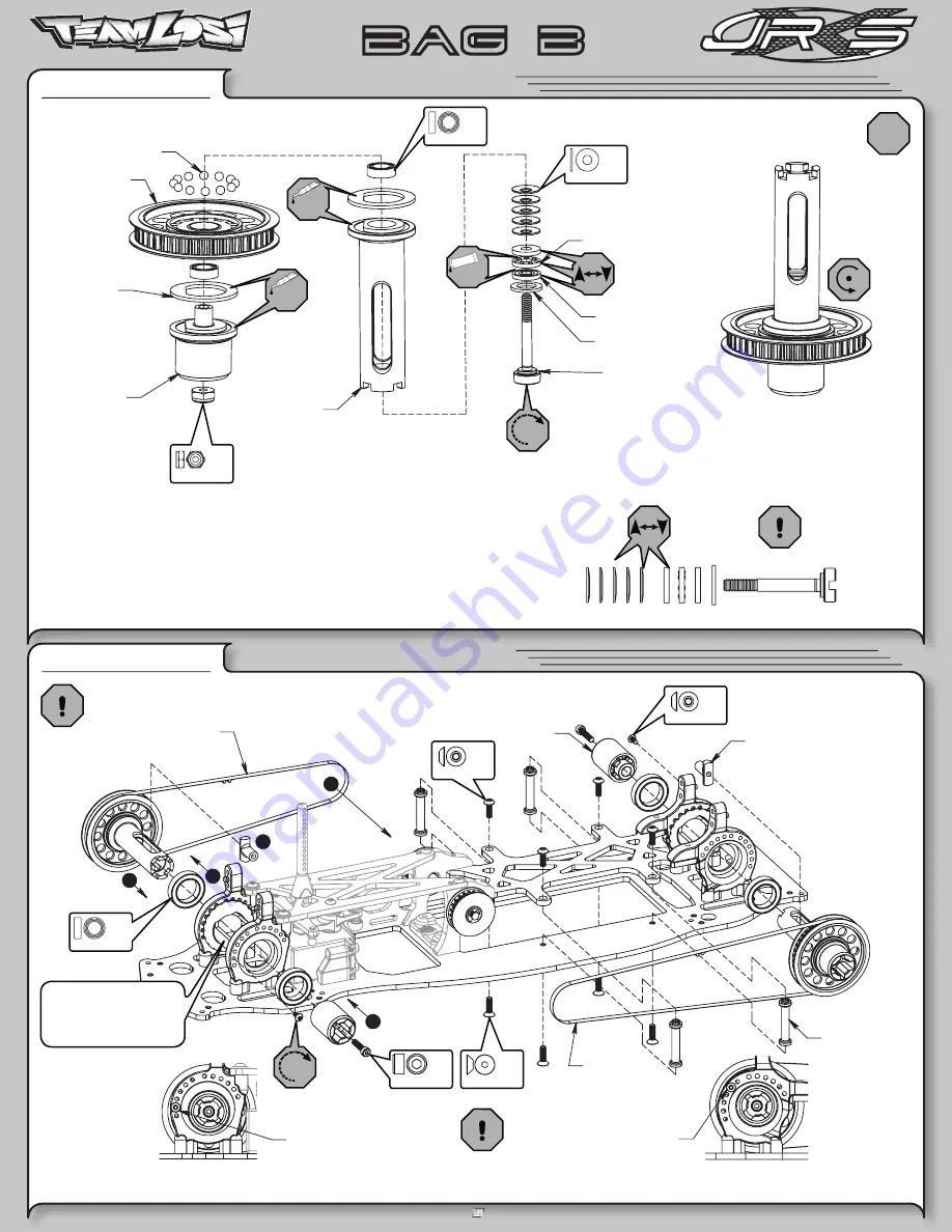
Thrust Washer
Diff Tube
A3315
Diff Screw
A3078
Foam Diff Seal
A3078
A3018
Caged Thrust Bearing
COMPLETED DIFFERENTIAL
A6951
A3070
Diff Pulley, 42T
A3211
Diff Ring
Carbide
3/32" Diff Ball,
A3310
Diff Outdrive,
Male
3
1
2
4
INITIAL REAR BELT
TENSION SETTING FOR
DIFF IN HIGH POSITION
(SEE SETUP GUIDE FOR ACENTRIC SETTING)
A3310
Diff Outdrive,
Diff T-Nut
A3312
5
(Grey)
Rear Drive Belt
A3302
(White)
Front Drive Belt
A3301
Female
A4314
Chassis Support
Post
INITIAL FRONT BELT
TENSION SETTING FOR
DIFF IN LOW POSITION
(SEE SETUP GUIDE FOR ACENTRIC SETTING)
DO NOT PINCH BELTS
4-40 x 5/16”
x4
4-40 x 3/8”
x4
It may be necessary to
temporarily rotate the Diff
Acentric into the HIGH
position to install the Diff.
Apply a small amount of Clear Diff Grease to the Diff Outdrive and the Diff Tube
before installing the Diff Ring.
Apply enough Clear Diff Grease to the top side of the Diff Rings, or to both sides of
recessed Ball section in the Diff Pulley (after Diff Balls are installed) to cover the
Diff Balls when the Diff is assembled.
Assemble the Diff and tighten until some resistance is felt, see the Final Checklist
for fi nal Diff adjustment procedures.
•
•
•
CAUTION!
Some Thrust Bearing assemblies
come bound with a small wire. This wire must be
removed before installing the Thrust Bearing.
BAG B
Differential Assembly
STEP B-03
Differential Installation
STEP B-04
L 4-40 x 1/4”
x1
5mm x 8mm
x2
GREASE
CLEAR
GREASE
CLEAR
GREASE
See Checklist, p.20
Belleville
x5
1
2
3
4
5
2-56 x 1/4”
x2
1/2” x 3/4”
x4
x2
4-40 x 1/2”
x2


