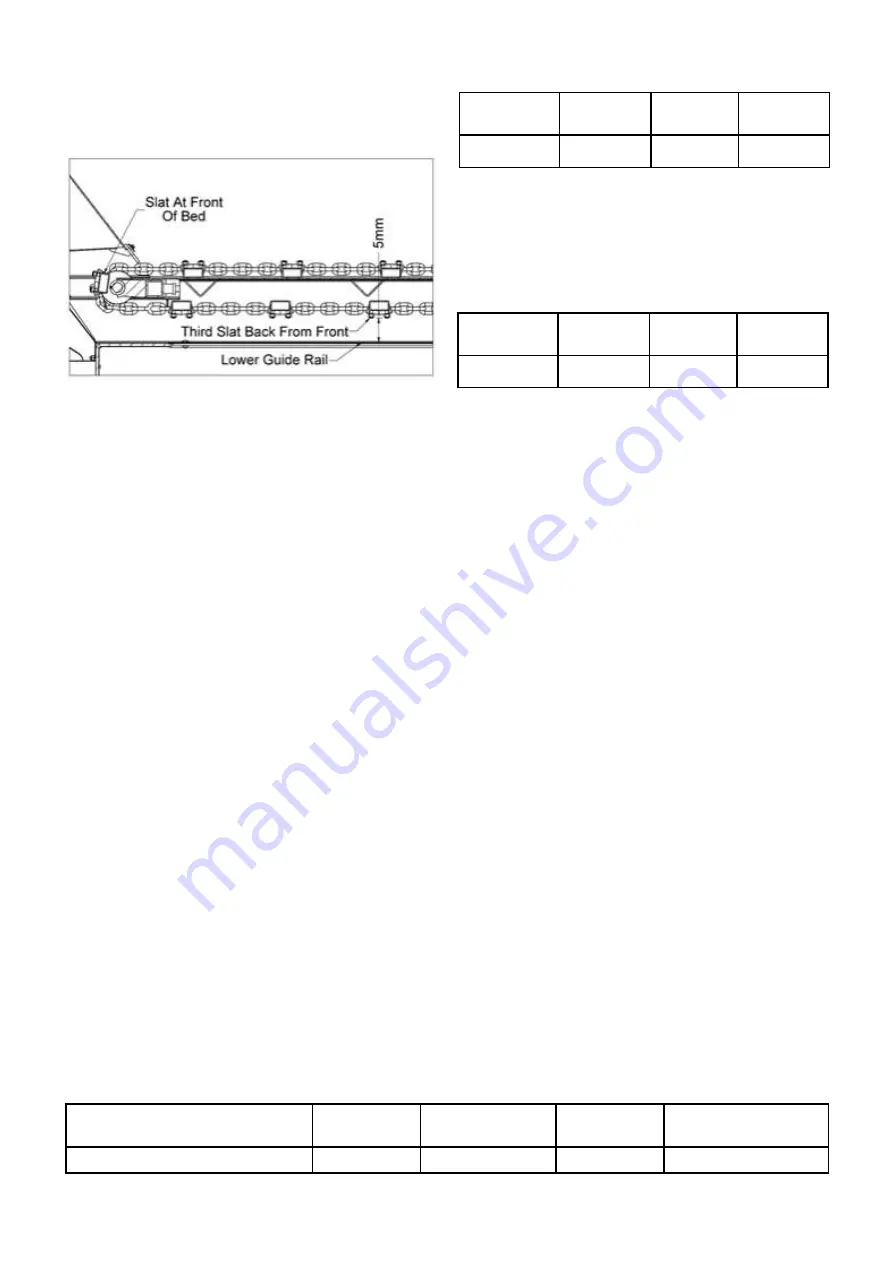
the machine approximately level with the centre of the
front cross shaft. The third slat underneath should be
5mm clear of the lower guide rail. Figure 4 illustrates
this. Check the tension on both the left and right hand
sides.
Figure 4 Correct bed conveyor tension
To increase tension, screw the tensioners forwards
and lock in position using the locking nuts. Check the
tension on both the left and right hand sides after
adjusting.
After a long period of use, the threaded screw
adjusters may reach the end of their travel. In this
instance, to gain more tension the conveyor will need
to be shortened. This is done by removing two links
from one of the chain sections from the same position
on both the left and right hand sides of the conveyor.
After re-bolting the shortened chain sections back into
the conveyor, re tension the threaded adjusters.
BEATERS
Regularly check the condition of the beaters and
repair any damage immediately. Severely worn tips
will adversely affect the spread pattern, reduce the
shredding of material and increase the power
requirement. Worn tips should be reversed or replaced
as necessary.
PTO DRIVELINE
The PTO shafts should be checked regularly and any
broken or damaged guards replaced. All joints should
be checked and replaced if damaged. Replacement
PTO parts including guards are readily available.
The optional ratchet clutch is totally enclosed and
does not require routine maintenance other than
lubrication.
AXLES, WHEELS & TYRES
The axle retaining bolts should have their torque
checked after the first 10 hour’s use and then every 50
hours. Table 1 gives the correct torque setting.
Table 1. Axle retaining nut and bolt torque setting
After the first hour’s use and then every 50 hours,
check the wheel nuts for tightness. If allowed to work
loose, the rims and wheel studs will become damaged
and it will be impossible to keep the wheel nuts tight.
The wheel nut torque setting is given in Table 2.
Table 2. Wheel nut torque setting
The removal, repair, refitting and inflation of a tyre can
cause accidents and this operation should be carried
out by a specialist tyre repairer.
Tyre inflation should always be carried out in a cage
with all personnel stood to one side, never in front.
When removing and refitting the wheels, ensure that
the machine is securely supported with the use of
correctly rated axle stands positioned on a level firm
surface. When the wheels are removed and
transported, they should be securely restrained and
checked for:
1. Damage to stud holes in the flange
2. Severe rust damage
The maximum inflation pressure for the standard tyre
size is given in Table 3.
AIR BRAKE SYSTEM
If the spreader is fitted with air brakes the air reservoir
requires draining daily, This is done by pulling down
on the ring at the base of the reservoir.
There is a manual load sensing valve fitted which
provides three levels of braking aggressiveness. The
setting is adjusted by rotating the lever fitted to the
valve. The least aggressive setting is suitable for
towing the spreader when empty. The most
aggressive setting should be used only when the
spreader is being towed laden.
A manual shunt valve is fitted in the air brake circuit.
When the button is pressed, the shunt valve releases
air pressure from the system so that the spreader can
be moved using a tractor fitted only with hydraulic
trailer brakes.
Socket Size
(mm)
Thread
(mm)
Torque
(lb/ft)
Torque
(Nm)
32
M22 x 1.5
332
450
Table 3. The maximum inflation pressure for the standard tyre size offered
Size
Ply Rating
Outside Diameter
(mm)
Width
(mm)
Max Inflation
Pressure
580/70 R38
R
1817
577
3.4 Bar (49 psi)
6
Socket Size
(mm)
Thread
(mm)
Torque
(lb/ft)
Torque
(Nm)
36
M24 x 3.0
332
450
Summary of Contents for TITAN 10
Page 1: ... _ _ _ _ _ _ _ _ _ _ _ _ ...
Page 50: ...47 NOTES ...
Page 51: ...48 WIRING DIAGRAM LED LIGHTS WIRING DIAGRAM TRACTOR LEAD ...
Page 52: ......


