background image

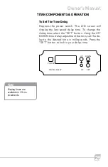
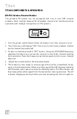
Depress  the  power  switch.  The  LCD  screen  will 

display  the  last  saved  delay  time.  To  change  the 

delay time select the “SET” button. Using the UP/

DOWN time delay adjustment buttons, set the de-

lay to the desired time in milliseconds. Press the 

“SET” button to lock in your delay time. 

25

Owner’s Manual

To Set The Time Delay

TITAN COMPONENTS & OPERATION

DIGITAL DELAY

POWER

UP

DOWN

AF

SET

Note

Display times are 
available in 1.9 ms. 
increments.

Summary of Contents for PA-849

Page 1: ...Owner s Manual Portable Wireless UHF Sound System...

Page 2: ...2 Titan product description INTRODUCTION Notes Date of Purchase Model Number Serial Number Notes ii...

Page 3: ...nt to uphold that confidence by providing factory assistance and dealer support We hope you will take the time to view this manual to familiarize yourself with the product features and its operation T...

Page 4: ...must be connected to an AC power source per the voltage input specified and marked on the power supply Power Cord Caution Power cable should be routed clear of foot traffic and supported clear of kink...

Page 5: ...nual Table of Contents INTRODUCTION Introduction Titan Components Operation Transmitter Microphones Battery Chargers Troubleshooting Accessories Specifications Warranty i 7 8 25 26 33 34 35 36 43 44 4...

Page 6: ...ther transmitting source This can show up as static interruption dropouts or even complete blockage To overcome interference change the channel to a non competing frequency Just like when you drive ne...

Page 7: ...rnal batteries are rechargeable and will operate the system for 4 6 hours Of course the Titan can be plugged into an AC outlet for continuous operation while also charging batter ies Batteries will be...

Page 8: ...AN COMPONENTS OPERATION Titan Rear Optional DR 750 Receiver Modules Optional CD MP3 Player Module Optional TX 750 Transmitter Module Charge Indicator Light Power Switch Main Control Panel 110 240v AC...

Page 9: ...e TX 750 transmitter module will broadcast a composite program signal to companion units equipped with a DR 750 wire less receiver The companion systems can be located throughout the venue without the...

Page 10: ...while in storage it will not damage or over charge the batteries and it will always be ready for use Lead acid batteries provide maximum performance relative to their size cost and weight The expecte...

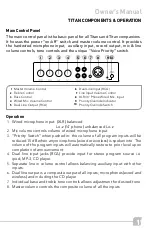
Page 11: ...oken into The volume of the program inputs will automatically restore to prior level upon completion of announcement 4 Dual line input jacks RCA provide input for stereo program source i e ipod MP 3 C...

Page 12: ...illuminate steady red 2 If plugged into AC power LED will glow Green if batteries are fully charged 3 If red indicator in switch flashes Indicates batteries are getting low and unit should be turned o...

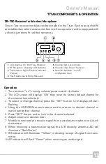
Page 13: ...row buttons set the receiver to desired channel or match transmitter channel 5 Press SET button and to lock in the channel selected 6 Adjust volume to desired level 7 Module is now ready to receive si...

Page 14: ...3 To select a channel press the SET button Using the UP DOWN frequency adjustment buttons you can set the receiver to match the channel used by the transmitter Press the frequency set button again to...

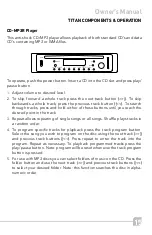
Page 15: ...sing the next track and previous track buttons Press repeat to enter the track into the program Repeat as necessary To playback programmed tracks press the play pause button Note program will be reset...

Page 16: ...ious track number FWD Press to desired next track number PLAY PAUSE Press once to play press again to pause STOP EJECT Press to stop playing press again to eject disc Infrared window Picks up signal f...

Page 17: ...t shows REPEAT 1 REPEAT ALL When all tracks are playing repeatedly it shows REPEAT ALL REPEAT FOLDER When all tracks in a specific folder are playing repeatedly it shows REPEAT FOLDER SHUFFLE Will pla...

Page 18: ...k To stop playback press STOP EJECT or press once on the remote controller To eject CD press STOP EJECT once to stop playback Press again to eject CD Or press on remote controller Press FB FF or on th...

Page 19: ...the card to the bottom and then release Please do not use force to pull card out Pulling the card will damage the card and or machine Press SD USB CD or SD USB CD on the remote controller Select SD th...

Page 20: ...rack number and selection number 2 Then press to confirm selec tion the LCD will display 01 42 02 This is Folder number 1 track number 42 second selection to play Then press 1 and 9 for track number t...

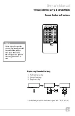
Page 21: ...ER CD USB SD 2 5 A B 8 0 NOR PROG EJECT PITCH RAN REP 3 6 9 HIGH Note When using the remote control the remote should be pointed toward the face plate of the CD MP3 Player The optimal receiving distan...

Page 22: ...the unit to the same channel as the master unit Press the frequency set button again to lock in your channel selection 5 When transmitting audio from the master to slave unit the TX indicator will li...

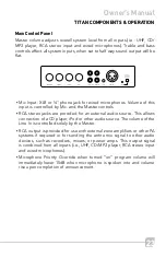
Page 23: ...ed for an external audio source This allows connection of a CD player iPod or other audio source The volume of the Line In is controlled solely by the Master RCA output is provided for use with extern...

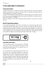
Page 24: ...t of the receiver is passed through the delay module in route to the power amplifier The purpose of the delay module is to store the signal momentarily and then pass it through to the amplifier input...

Page 25: ...SET button Using the UP DOWN time delay adjustment buttons set the de lay to the desired time in milliseconds Press the SET button to lock in your delay time 25 Owner s Manual To Set The Time Delay T...

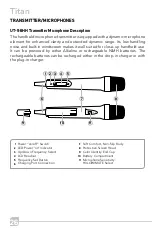
Page 26: ...handheld use It can be powered by either Alkaline or rechargeable NiMH batteries The rechargeable batteries can be recharged either in the drop in charger or with the plug in charger HI LOW MUTE Powe...

Page 27: ...will also display Battery condition and CH 10 A microphone sensitivity selection switch provides three modes of microphone sensitiv ity HIGH LOW MUTE MUTE Mutes microphone off while retaining transmis...

Page 28: ...rn off to prevent damage 14 To turn microphone off press and hold the power switch until the LCD screen displays OFF FCC Regulation RF transmission equipment must comply with FCC regulations All Teach...

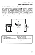
Page 29: ...h a boom microphone The transmitter is usually worn on the waist utilizing the wire belt clip however it can be placed in your pocket if it is more convenient The Body Pack is battery powered and requ...

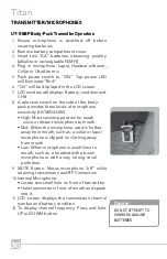
Page 30: ...microphone sensitivity HI MID LOW High Most sensitive position for weak voice or distant microphone to mouth Mid When the microphone used is further away from mouth such as a collar or lapel microphon...

Page 31: ...s is displayed on the left edge of the LCD screen When battery nears depletion Icon will flash 3 times Transmitter will automatically turn off to prevent damage 15 To turn microphone Off push power sw...

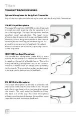
Page 32: ...adjust ment of volume is more critical especially near or under a speaker HBM 935 Headband Microphone The Headband Microphone HBM 935 is worn around the head with a unidirectional microphone located...

Page 33: ...mfortable and inconspicuous It is avail able in either beige or black LM 300 Plug In Microphone w Lanyard The Plug in Microphone LM 300 is a small capsule size microphone that plugs directly into the...

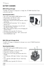
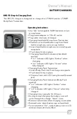
Page 34: ...e into jack at the base bottom end of transmitter Turn Handheld Transmitter On to observe battery icon During charging the battery icon will cycle through the charge block When fully charged battery i...

Page 35: ...e Charging Handheld Indicators Handheld symbol on indicator LED lights Amber when charging ok indicator LED lights Green when fully charged Charging Body Pack Transmitter Insert Body Pack into Front L...

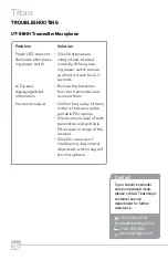
Page 36: ...ng power switch LCD panel displays garbled information No sound output Check batteries are charged and inserted correctly When press ing power switch ensure you hold it down for 2 3 seconds Remove the...

Page 37: ...s includes Microphones Televisions Radio Stations etc When operating two trans mitters in the same area ensure frequencies selected are several channels apart This helps to reduce cross talk between t...

Page 38: ...ton is not activated Ensure body pack is within range of the receiver Check for sources of interference large metal objects etc within range of the body pack When operating two transmitters in the sam...

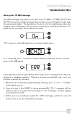
Page 39: ...ring Error message to the devices software or hardware problem Following instructions will lead you to sort out problems caused by software 1 RESET built in software by pressing and holding SET UP DOW...

Page 40: ...Titan product description TROUBLESHOOTING...

Page 41: ...to operate with each other simultaneously Note When interference problem is encountered verify that the microphones are operating on frequencies in the same cluster 41 Owner s Manual TROUBLESHOOTING 1...

Page 42: ...42 Titan product description TROUBLESHOOTING Channel Frequency Allocation 640 664 MHz LCD UHF TV Frequencies TV Channel 42 43 44 45 46 MHz 638 644 644 650 650 656 656 662 662 668...

Page 43: ...43 Owner s Manual TROUBLESHOOTING...

Page 44: ...microphone has very low handling noise a built in breath filter and wide dynamic range The Spartan is a portable battery AC operated sound system with 20 watt RMS amplifier Weighing only 6 pounds it s...

Page 45: ...45 Owner s Manual ACCESSORIES...

Page 46: ...sis Sensitivity Squelch Frequency Response Operating Power Operating Range Power Requirements 50 Watts 108 dB 70Hz 20kHz 8 woofer 1 horn 70 dB 91dB 1 watt 1 meter Mic XLR w Volume Control Line RCA w V...

Page 47: ...Wireless Receiver CD MP3R Player DD 750 Digital Delay TX 750 Wireless Transmitter 47 Owner s Manual SPECIFICATIONS Delay Range Increments Dimensions Weight Dimensions Weight Formats Media 20 500 ms 1...

Page 48: ...nsions Weight with batteries Mic Capsule RF Output Spurious Emission AF Controls Battery Operating Life fully charged Dimensions Weight with batteries Dynamic 10mW 250mW Hi lo mute switch 1 2V NiMH re...

Page 49: ...not extend to finish or appearance past ninety 90 days 7 All warranty service will be provided by TeachLogic or authorized service center 8 Warranty is made to the original purchaser and may not be tr...

Page 50: ......

Page 51: ......
Page 52: ...TeachLogic Inc 1688 Ord Way Oceanside CA 92056 1 800 588 0018 sales teachlogic com 1 760 631 1283 www teachlogic com...

Reviews: