


r 2022.10.21 Page 7
RS
-
232 Control and Switch
•
There is a 6
-
pin green terminal block connector with 3 contacts labeled
RS232
(#8 on the back panel of Diagram 1) that provide a
connection for a third
-
party RS232 control device to be used with the OA
-
50.
•
There is a switch labeled
RS232 SWITCH OFF / ON
directly to the left of the green terminal block connect-
or
.
When using a RS232 control device, ensure the RS232 switch is in the ON position. This will direct the
OA
-
50 to take commands from the panel. If you are not using a control panel, switch to the OFF position.
•
The RS232 command list is available from TeachLogic
Note:
When the RS232 switch is set in the ON position, front panel volume controls on the OA
-
50 are
defeated and will not work.
Fire Alarm Mute Input
•
The 2
-
pin orange terminal block connector labeled
Fire Alarm Mute Input
(#2 on back panel in Diagram 1) provides
a connection to mute the OA
-
50. If a connected fire alarm system is in alarm mode, this will mute all audio in the
OA
-
50 amplifier. This feature will help lower the overall sound level to allow students and staff hear the audible
fire alarm tones and instructions within the classroom.
Note:
The Page Pass Through audio is muted during alarm.
•
Audio will resume at original volume 11 seconds after fire alarm input stops receiving a signal. The signal is a dry contact closure.
Note:
This feature only works if your school connects their fire alarm system to the OA
-
50.
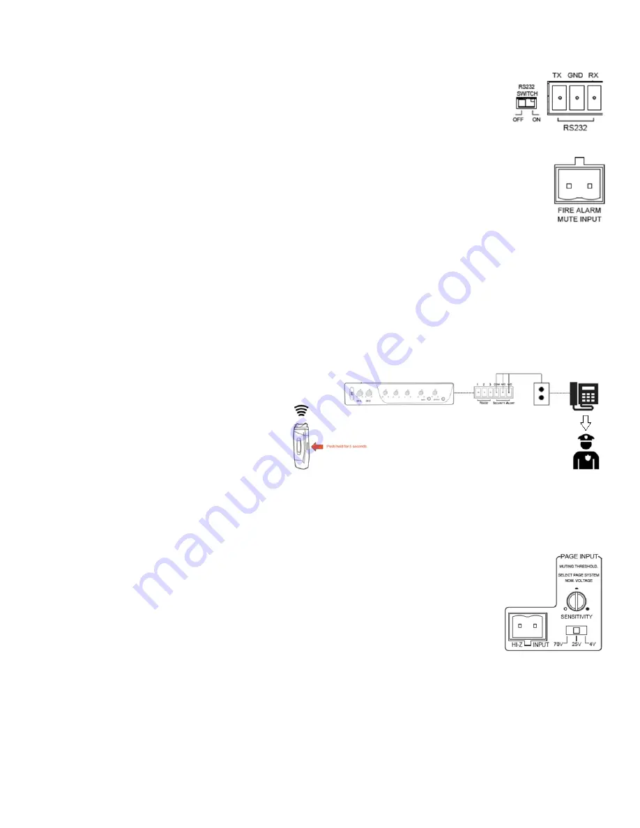
Security Alert Activation and Settings
•
The Security Alert feature allows a user with a TeachLogic wireless pendant microphone to summon help or alert admin-
istration personnel to an urgent situation in the room of that user. This feature uses wire from the school
’
s paging or secu-
rity system (such as a wall
-
mounted call button panel) to connect to the OA
-
50 receiver via the 2 or 3 contacts on the 6
-
pin
terminal block connector (#9 on the back panel of Diagram 1).
•
To activate the security alert (your OM
-
10 pendant microphone must be on and connected to your OA
-
50), push and hold the OM
-
10’
s AUDIO spring switch for 5 seconds. The OM
-
10 main (logo) button will flash green 3x once an alert is activated. Your OA
-
50
logo button will do the same.
Note:
The OA
-
50 will function normally during the
ale rt, i.e., there is no change the volume or to
audio input/output. The system will not pro-
duce any sound besides a quiet clicking noise
(1 or 4 times) from the OA
-
50 itself.
•
There are two security alert pulse modes, 1
-
pulse or
4
-
pulse, as required for different security systems.
You can switch between the two settings via the
slide switch on the left side of your OA
-
50 (center
left switch on Diagram 2) or the bottom of your OA
-
50 for the setting instructions.
Note:
Ensure you use a non
-
metallic object to manipulate the switch.
Page Mute vs Page Pass Through
•
Page Pass Through is a feature that passes an audio paging signal through the amplifier and to the connected loudspeakers.
•
Page Mute will mute any audio signal passing through the OA
-
50 (except for a page signal) whenever a page is
detected on the separate paging system.
•
Page Pass Though may be switched on or off by moving a side panel switch up or down center right switch in
Diagram 2). This switch position guide is also located on the bottom of your OA
-
50.
•
Page Mute is controlled by a sensitivity dial (#4 on the back panel of Diagram 1) and by a switch set to the
Nominal voltage level of the paging system (#5 on the back panel in Diagram 1).
•
The impedance of the page system input port (2
-
pin green terminal block connector) is >50,000 ohms.
Using the OP
-
10 Control Panel
•
If your OA
-
50 needs to be placed in an area or compartment that is not easily accessed by the user, an OP
-
10 Wall Mount Control
Panel can be used to allow limited remote controls. These include pairing and un
-
pairing microphones from an OA
-
50, turning an
OA
-
50 On and Off, putting the OA
-
50 into or out of Standby Mode, and radio
-
resetting the OA
-
50. Please refer to Diagram 3 in con-
junction with the instructions below.
•
Lights on the OP
-
10 indicate pairing and connection status by duplicating certain illuminations of the front panel pairing indicators
on the OA
-
50 (#3 & #5 on the front panel in Diagram 1).
•
The indicator light next to the OP
-
10 power button mimics that on the OA
-
50 logo button showing solid blue (On), slow
-
blinking
blue (Standby), no light (Off), and blinking blue (Radio Reset).
Note:
If radio (RIB) reset is occurring all three LED indicator lights (#4, #5, and #6 on Diagram 3) will blink 3x.
•
Pressing an OP
-
10 pair button has the same effect as pressing a pair button on the OA
-
50.
•
Pressing the power button on the OP
-
10 has the same effect as pressing the logo button on the OA
-
50.


