NOTE
i
408-1610
8 of 11
Rev M
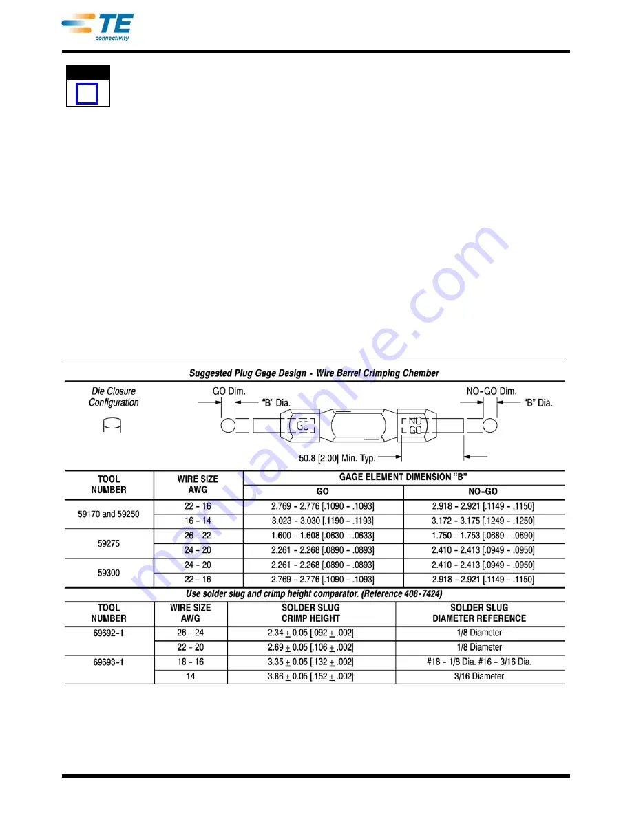
Refer to the table in Figure 11 for alternate hard
gage dimensions for tools 69692-1 and 69693-1.
A. Gaging the Crimping Chamber Using A Plug Gage
This inspection requires the use of plug gages
conforming to the dimensions listed in Figure 9 and
Figure 10. Tyco Electronics does not manufacture or
market these gages. Refer to 408-7424 for information
concerning plug gages
To gage the crimping area(s), refer to Figure 12 and
proceed as follows:
1. Clean oil or dirt from the crimping chamber and
plug gage.
2. Close handles of tool until wire barrel dies are
bottomed. Do not apply additional pressure to tool
handles.
3. With wire barrel dies bottomed, inspect the wire
barrel crimping chamber using the proper plug
gage. Lift the spring-loaded locator up and hold
gage in straight alignment with the crimping
chamber. Carefully try to insert, without forcing, the
GO element. See Figure 12, Detail A. The GO
element must pass completely through the crimping
area.
4. Try to insert the NO-GO element. The NO-GO
element may enter partially, but must not pass
completely through the crimping area.
5. Set insulation adjustment indicator in Position 1.
Measure both insulation crimping chambers with the
proper GO plug gages in the same manner as Steps
2 and 3. See Figure 12, Detail B.
6. Set insulation adjustment indicator in Position 4.
Measure both insulation crimping chambers with the
proper NO-GO plug gages in the same manner as
Steps 2 and 4. See Figure 12, Detail B.
If the crimping areas conform to the gage inspection,
the tool is considered dimensionally correct. If the
crimping areas do not conform to the inspection, the
tool must be repaired. Refer to Section 8,
REPLACEMENT AND REPAIR.
Figure 9


