408-1536
Rev J1
5
of 7
Gaging the Crimping Chamber
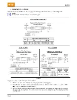
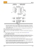
This inspection requires the use of a plug gage conforming to the dimensions provided in Figure 5.
NOTE
TE Connectivity does not manufacture or market these gages.
For Tools 46073 and 46074
Tool
Gage Element Diameter mm [inch]
GO
NO-GO
46073 2.464-2.471 [.0970-.0973] 2.614-2.616 [.1029-.1030]
46074 2.997-3.005 [.1180-.1183] 3.147-3.150 [.1239-.1240]
For Tool 46073
For Tool 46074
Figure 5
To gage the crimping chamber, proceed as follows:
1. Remove traces of oil or dirt from the crimping chamber and plug gage.
2. Close the tool handles until it is evident that the dies have bottomed; then hold in this position.
DO
NOT
force the dies beyond initial contact.
3. Align the GO element with the wire barrel crimping section. Push element straight into the crimping
chamber without using force. The GO element must pass completely through the crimping chamber
(see Figure 6).

