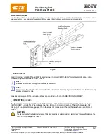
408-1536
Rev J1
2
of 7
CRIMPING PROCEDURE
NOTE
Each hand tool is coated with a preservative to prevent rust or corrosion. Wipe this preservative from
the tool, particularly from the dies, before using the tool.
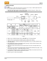
1. Select the correct splice for the wire size and wire insulation diameter being used. Observe color
coding of splice, rings, adaptors, and tools (see Figure 2).
Wire
Splice
Splice
Wire Strip
Length
mm [inch]
Splice Body
and Tool
Color Code
Tool
Adapter
Ring Color
Size Range
(AWG)
Max Insul
Diameter
mm [inch]
A
B
C
D
24-20
1.65 [.065]
324987
Yes Yes
Green
Green
7.37 [.290]
Tin
(White)
46073
1.85 [.073] 1-324987-0
Orange Orange
1.85 [.073]
1-324987-1
---
Yes
---
Orange
2.54 [.100]
---
---
Tin
---
6.35 [.250]
2.54 [.100]
324544
---
Tin
20-18
2.57 [.101]
324988
Yes Yes Green
Green 7.87 [.310]
Red
46074
3.38 [.133]
324548
---
---
Tin
Tin
7.11 [.280]
Figure 2
2. Strip the wire to dimensions listed in Figure 2.
DO NOT
nick or cut the wire strands.
3. Open the dies by squeezing the tool handles together until the ratchet releases.
4. Select the proper color-coded end of splice (when applicable) for the wire insulation diameter being
used (see Figure 2).
5. Insert stripped wire into splice until it bottoms against wire stop. End of conductor should be visible
through transparent window indent of splice.
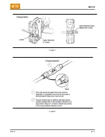
6. Align splice window indents with tool locator, and push splice into locator until splice bottoms (see
Figure 3).
7. Hold wire in place and squeeze tool handles together until the CERTI-CRIMP ratchet releases. Allow
tool handles to open FULLY. Crimped splice may be removed.
8. To crimp other half of splice, position uncrimped half in tool and follow same procedure used to crimp
first half of splice. If splice cannot be turned, turn tool around.
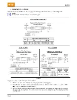
9. Refer to Figure 4 for splice crimp inspection.

