background image

System 3

6-9

PZ2 PreAmp

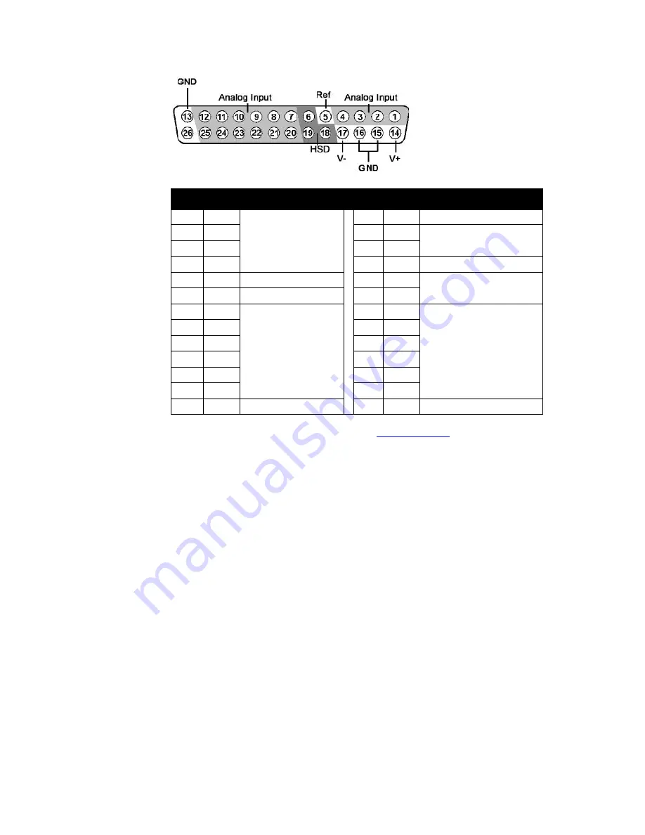
Pinout


Diagram

Note:

TDT technical support (386-462-9622 or 

[email protected]

) before attempting to 

make any custom connections to pins 6, 18, or 19. 

Pin

Name

Description

Pin

Name

Description

1

A1

Analog Input Channels

14

V+

Positive Voltage (+1.5V)

2

A2

15

GND

Ground

3

A3

16

GND

4

A4

17

V-

Negative Voltage (-1.5V)

5

Ref

Reference

18

HSD

Headstage Detect

6

HSD

Headstage Detect

19

HSD

7

A5

Analog Input Channels

20

A6

Analog Input Channels

8

A7

21

A8

9

A9

22

A10

10

A11

23

A12

11

A13

24

A14

12

A15

25

A16

13

GND

Ground

26

NA

Not Used

Summary of Contents for PZ2

Page 1: ...channel models Note When sampling at a rate of 50 kHz only the first 128 amplifier channels will be available System Hardware All PZ2 channels are organized into groups of 16 channel banks with each b...

Page 2: ...hile collecting data Powering ON To turn the preamplifier on move the three position battery switch located on the front panel of the PZ2 to either the Bat A or Bat B position Powering OFF To turn the...

Page 3: ...o indicate a clip warning Green Activity Red Clip Warning Clip Warning When the input to a channel is greater than 3dB from the preamplifier s maximum voltage input the LED for the corresponding chann...

Page 4: ...eads to remove any potential RF noise that might travel through the cable For best results position the ferrite bead close to the source of the RF noise Battery Overview The PZ2 preamplifier features...

Page 5: ...indicator denotes the battery bank is fully charged while a red indicator designates the battery is currently charging When the device is in operation charger is not connected the A and B LEDs are not...

Page 6: ...on all headstages should be connected together to form a single common ground See Headstage Connection Guide on page 6 99 Distortion typical 1 A D Sample Rate Up to 48828 125 Hz Sample Delay Dependen...

Page 7: ...me Description Pin Name Description 1 A1 Analog Input Channels 14 V Positive Voltage 1 5V 2 A2 15 GND Ground 3 A3 16 GND 4 A4 17 V Negative Voltage 1 5V 5 Ref Reference 18 HSD Headstage Detect 6 HSD H...

Page 8: ...6 10 System 3 PZ2 PreAmp...

Reviews: