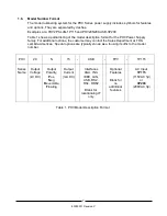
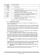

17
83550001 Revision C
REF
DESCRIPTION
NOTE
SECTION
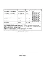
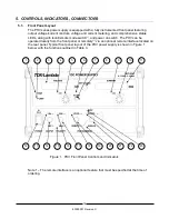
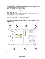
1
Overtemp LED
Indicates an Overtemperature condition
2
P-Limit LED
Illuminated for
optional
Power limit mode
3
Voltage Display
Indicates actual output voltage, displays set point when
flashing
4
CV LED
Illuminated for Constant-Voltage mode operation
5
Output Voltage
Control
Lockable 10-turn Potentiometer for output voltage set value
6
OVP LED
Indicates OVP limit has been reached
7
OVP Limit Point
OVP set point potentiometer (screwdriver adjustable, 1-turn)
8
Set Value button
Switches the output displays to set point mode. Displays will
flash when in set point mode.
9
CC LED
Illuminated for Constant-Current mode operation
10
Output Current
Control
Lockable 10-turn Potentiometer for output current set value
11
Current Display
Digital display of average output current
12
Power switch
Turns on/off Main AC power to unit
13
HV ON LED
Illuminates when HV output is turned ON
14
HV ON/OFF Button
Turns HV Output ON/OFF (does not disconnect the HV
output, or AC Input)
15
NEG Polarity LED
(1)
If
optional
polarity reversal is installed, Illuminates to
Indicate the output polarity is Negative
16
POS Polarity LED
(1)
If
optional
polarity reversal is installed, Illuminates to
Indicate the output polarity is Positive
17
Polarity Button
(1)
Controls the HV output polarity if
optional
polarity reversal
is installed
18
Local LED
(1)
Indicates Local control is enabled
19
Local Remote
Switch
(1)
Toggles the control mode between Local and Remote
control mode
20
Analog LED
(1)
Indicates Remote Analog control is enabled
21
Analog/Digital
Remote Switch
(1)
Toggles the control mode between Remote Analog or Digital
if an
optional
digital interface is installed
22
Digital LED
(1)
Indicates Remote Digital control is enabled if an
optional
digital interface installed
23
Busy LED
(1)
Indicates presence of traffic on the
optional
digital interface
Table 3. Front Panel Controls and Indicator Functions (includes optional features)
Note 1. Indicates an optional feature that may not be installed.
Summary of Contents for PHV Series
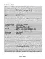
Page 11: ...8 83550001 Revision C 2 SPECIFICATION...
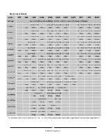
Page 12: ...9 83550001 Revision C Mechanical Details...
Page 14: ...11 83550001 Revision C This Page Left Intentionally Blank...
Page 26: ...23 83550001 Revision C This Page Left Intentionally Blank...
Page 32: ...29 83550001 Revision C This Page Left Intentionally Blank...
Page 34: ...31 83550001 Revision C This Page Left Intentionally Blank...
Page 36: ...33 83550001 Revision C This Page Left Intentionally Blank...
Page 37: ...34 83550001 Revision C Notes...