83-517-000 Rev.
A
23
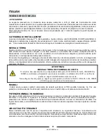
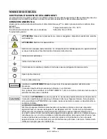
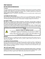
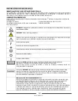
WARNING
There is a potential shock hazard if the power supply chassis (with
cover in place) is not connected to an electrical safety ground via
the safety ground in the AC input connector.
CAUTION
Ensure that the screws used to attach the slides to the unit do not
penetrate more than 6mm into the sides of the unit.
Rack-Mount Slides (optional):
3.4.2
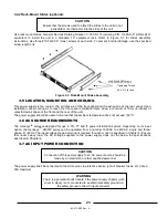
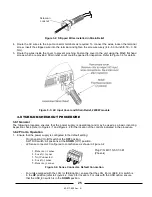
Use rack mount slides: General Devices Catalog Number: C-300-S-116 (ordering P/N: C-300-S-116-RH-LH) or
equivalent to install the unit in a standard 19” equipment rack. Refer to Figure 3-1 for slides assembly
instructions. Use three #10-
32x0.38” (max.) screws at each side. To prevent internal damage, use the specified
screw length only.
Figure 3-1: Rack-Mount Slides Assembly
3.5
LOCATION, MOUNTING AND COOLING
This power supply is fan cooled. The air intake is at the front panel and the exhaust is at the rear panel. Upon
installation, allow cooling air to reach the front panel ventilation inlets. Allow a minimum of 10cm (4 inches) of
unrestricted air space at the front and the rear of the unit.
The power supply should be used in an area that the ambient temperature does not 50°C.
3.6
AC SOURCE REQUIREMENTS
The Genesys
TM
series is designed for use in TN, TT and IT power distribution system. Depending on its input
option, the Genesys
TM
2400W series can be operated from a nominal 190VAC to 240VAC, single and three-
phase, 47~63Hz. The input voltage range and current required for each model is specified in Chapter 2. Ensure
that under heavy load, the AC voltage supplied to the power supply does not fall below the specifications
described in Chapter 2.
3.7
AC INPUT POWER CONNECTION
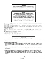
The power supply shall be connected to the AC source via protective device (circuit breaker, fuses, etc.) rated
30A maximum.
Tightening Torque
24.4-31.7 lb.-inch
CAUTION
Connection of this power supply to an AC power source should be
made by an electrician or other qualified personnel

