background image


12 


83488001 Revision N 


diodes.  Make sure the load (capacitor) is connected and the HV output cable is 
securely inserted and connected. 

3.  Turn the voltage control on the front panel all the way down to zero (counter 

clockwise), apply AC power, turn the front panel keyswitch to the LOCAL position (if 
applicable), and press the HV ON button.  By turning up the HV control knob the 
capacitor will charge to the voltage indicated on the front panel voltmeter.  The 
power supply may be turned all the way up to its max. output voltage provided the 
load capacitor is sufficiently rated. 

4.  By turning the voltage control down or depressing the HV OFF button, the capacitor 

will slowly "bleed" down through the internal voltage divider resistors used for 
regulation feedback. Use an external discharge wand to ensure the capacitor is fully 
discharged. 

Test #2 indicates the HV section is working correctly.  Tests 1 and 2 generally indicate 
the unit is functioning as designed.  Although 100% power had not been generated, 
these two tests give greater than 90% confidence that the unit is not damaged. 

If any inconsistency from the above test procedure is noted, do not hesitate to call TDK-
Lambda Americas Customer Service for assistance.  

3.3. 

Contacting TDK-Lambda Americas Customer Service 

When contacting customer service locate the product description, part number and serial 
number from the label located on the rear of the unit, and have this information available. 

Phone:  (732) 922-9300      

E-mail:  [email protected] 

Fax:       (732) 922-1441 

Customer Service, or an approved Service Center, should be contacted if: 

  The power supply is mechanically or electrically damaged. 

  The power supply requires on-site calibration, or replacement warning decals. 

  The customer has questions about a special application that is not described in this 

manual. 

Normally, the customer may 

NOT 

open any chassis covers that have a warranty seal. 

Breaking a seal will void the warranty.  

At the discretion of TDK-Lambda Americas, the customer may be granted permission to 
break the warranty seal and open the chassis covers. Customer Service shall confirm the 
permission by sending a replacement seal. Once the unit has been serviced, the customer 
shall close the cover and apply the replacement seal adjacent to (not on top of) the broken 
seal. 

3.4. 

Returning Defective Units 

If a unit needs to be returned to the factory for repair, the factory must first assign an RMA 
number. Please complete and send the online RMA request form at 

http://www.us.tdk-

lambda.com/hp/RMA_request.htm

 and an RMA number will be assigned. Follow the return 

instructions on the form or at http://www.us.tdk-lambda.com/hp/returns.htm. 


Summary of Contents for 802 Series

Page 1: ...OPERATOR MANUAL FOR 802 Series High Voltage POWER SUPPLY Document 83488001 Rev N TDK LAMBDA AMERICAS 405 Essex Road Neptune NJ 07753 Tel 732 922 9300 Fax 732 922 9334 Web www us tdk lambda com hp ...

Page 2: ...PAGE LEFT INTENTIONALLY BLANK ...

Page 3: ...HAL VOLTAGES PRESENT All power supplies contain hazardous voltage and energy The power supply must only be operated by qualified personnel who have read this operator s manual and are familiar with the operation hazards and application of the power supply Proper care and judgment must always be observed 1 Before connecting input AC power ensure all covers are in place and securely fastened Ensure ...

Page 4: ... as defined by TDK Lambda Americas Inc for the products described by this manual is stated as follows The Power Supplies described by this manual are intended for use in a protected industrial environment or in proximity to industrial power installations These locations are often referred to as industrial locations containing establishments that are not connected to the low voltage public mains ne...

Page 5: ...tive 93 68 EEC European Community Conformity Assessment Product Mark IEC 348 Attention consult Accompanying documents IEC 60417 1 5036 Dangerous voltage IEC 60417 1 5019 Protective earth e g power line earth ground IEC 60417 1 5017 Functional earth e g chassis ground IEC 60417 1 5134 Electrostatic Discharge ESD Sensitive Device ...

Page 6: ...ipment to the factory the following steps shall be taken 1 Notify TDK Lambda Americas Inc at 732 918 6888 or follow the instructions at www US TDK Lambda com HP service htm Give a full description of the difficulty including the model and serial number of the unit in question Upon receipt of this information we will assign a Return Material Authorization RMA number and provide shipping instruction...

Page 7: ...9 2 11 AC Line Contactor 9 2 12 Power Factor 9 2 13 Efficiency 9 2 14 Front Panel 9 2 15 Stability 9 2 16 Temperature Coefficient 9 2 17 Stored Energy 9 2 18 Pulse to Pulse Repeatability 9 2 19 Dimensions inches mm 9 2 20 Weight lbs kg 9 2 21 Ambient Temperature 9 2 22 Altitude 9 2 23 Humidity 9 2 24 Protection 9 2 25 Remote Control all models 9 2 26 Accessories 9 2 27 Options 10 2 28 Ordering Inf...

Page 8: ...witch Ref 7 21 5 9 View set push button Ref 8 21 5 10 Current bar graph Ref 9 21 5 11 Current Display Ref 10 22 5 12 Power switch Ref 11 22 5 13 Front Panel Layout S Model 22 5 14 Front Panel Layout OEM Model 22 5 15 Rear Panel Layout L Models 23 5 16 Rear Panel Layout S Models 25 5 17 Rear Panel Layout OEM Models 26 5 18 REMOTE CONTROL CONNECTOR PIN DIAGRAM 27 6 OPERATING INSTRUCTIONS 29 6 1 Loca...

Page 9: ...ote Interface Connector and Signals 27 Figure 12 Suggested external remote interface circuit 31 Figure 13 Typical remote Interface waveforms 34 Figure 14 802L Parallel System Control Connections 35 Figure 15 802L and 802S OEM Parallel System control Connections 36 Figure 16 Parallel Operation Connections for 802S OEM Supplies 37 List of Tables Table 1 802 Model Description Format 8 Table 2 Recomme...

Page 10: ...4 83488001 Revision N Notes ...

Page 11: ... a broad range of pulse generator circuits without the need for a series current limiting resistor They can also be used in many continuous DC applications including beam power for RF devices such as magnetrons gyrotrons klystrons and electron beam loads The 802 series utilize a high frequency IGBT based series resonant inverter topology which operates as a constant current source This makes the s...

Page 12: ...ies allow capacitors to be charged in pulse forming networks and modulators in a very fast efficient and controllable manner The units are compact high power constant current sources that can linearly and rapidly charge a capacitive load to high voltage Once the load capacitor is charged to the programmed voltage the supply will switch over to a voltage regulation mode and maintain the load voltag...

Page 13: ...y Precautions All 802 power supplies are designed to minimize the risk of fire or shock hazard This instrument received comprehensive mechanical and electrical inspection prior to shipment Nevertheless certain safety precautions must be observed Only TECHNICALLY QUALIFIED SERVICE PERSONNEL familiar with the principles of electrical safety should operate this supply The power supply SHOULD NOT BE E...

Page 14: ...ld only be serviced by factory authorized personnel 1 7 12 No user maintenance is required 1 8 Model Number Format The model numbering system for the 802 Series power supply includes symbols for features and options They are separated by dashes Examples are 802L 10kV POS 400VAC and 802S 20kV POS DC The 802 is available with three front panel configurations the L S and OEM The choice of panel confi...

Page 15: ...Line Contactor UL CSA approved AC line contactor standard on 802L and 802S option for 802OEM 2 12 Power Factor Passive PFC pf 0 85 at full load and nominal AC line 2 13 Efficiency Better than 85 at full load 2 14 Front Panel 802L Voltage Control Voltage Current Meters Status Indicators 802S On Off Switch Status Indicators 802 OEM Blank front panel 2 15 Stability 0 2 per hour after 1 hour warmup 2 ...

Page 16: ...quires HV reset after overload fault DC Continuous DC operation CT AC line contactor option for 802 OEM only standard on 802L and 802S Double terminated HV cable and mating bulkhead connector 2 28 Ordering Info Model XXkV POS or NEG YYYVAC ZZ options 2 29 Ordering Examples 802L 10kV POS 802S 1kV NEG DC 802 OEM 50kV POS 400VAC All specifications subject to change without notice ...

Page 17: ...low the unit to generate full output current at zero voltage 1 Set the output voltage control to zero Connect AC power to the unit Turn ON the AC power front panel switch 2 Turn the front panel keyswitch to the LOCAL position if applicable Press the HV ON button and turn up the HV control until the power supply is generating output current into the dead short The current meter will indicate max cu...

Page 18: ...ing TDK Lambda Americas Customer Service When contacting customer service locate the product description part number and serial number from the label located on the rear of the unit and have this information available Phone 732 922 9300 E mail hp service us tdk lambda com Fax 732 922 1441 Customer Service or an approved Service Center should be contacted if The power supply is mechanically or elec...

Page 19: ...rical shock and protect the supply from environmental contamination Never install the 802 so its weight is supported only by the front panel screws The 802 must never be installed without support in the back or sides of the unit The 802 should be mounted on support rails or chassis slides such as General Devices CTS 124 or on a suitable shelf or supports inside the rack The mechanical outline of t...

Page 20: ...14 83488001 Revision N Figure 2 802L Rear View Figure 3 802L Side View 4 5 114mm 2 15 55mm 19 483mm 17 432mm 1 875 48mm 17 432mm ...

Page 21: ...C For 380 440VAC models the maximum voltage allowed between any two AC input terminals is 460VAC If this voltage is exceeded catastrophic damage will result that is not covered by TDK Lambda Americas standard warranty The customer s AC power line connects to the 802 via a UL CSA approved 5 position terminal block on the rear panel of the unit see Figure 1 Only use a power cable with the correct vo...

Page 22: ...Block If the power supply was purchased with the 400VAC input configuration in addition to the three phases the neutral wire must be connected to terminal marked N Failure to connect the Neutral wire in a 400VAC unit may result in damage to the supply AC INPUT VOLTAGE MODE RECCOMENDED AC INPUT CABLE SIZE RATING 200 240VAC 180 264VAC 50 60 Hz 3 Cap Charging 9mm 2 8 AWG 600V Continuous DC 9mm 2 8 AW...

Page 23: ...g DC 4 must be applied to the HV cable before insertion into the HV connector The grease is used to displace air in the connector and reduce long term corona effects A cable greasing procedure is available for download from the TDK Lambda Americas web site The load ground must be connected to the chassis ground through a separate safety ground cable with a minimum wire size of 10 AWG in addition t...

Page 24: ... cable jacket shield and any semiconducting layer if applicable that remains on the cable insulation after removing the shield The cable outer jacket should be removed to reveal the cable shield At least 12 or 300mm of outer jacket should be removed for suitable voltage hold off The exposed shield should be trimmed to an appropriate length and terminated with a ground connection For models shipped...

Page 25: ...atus LEDs Indicates status of supply and presence of any faults 5 3 3 Local Voltage Set 10 turn pot for setting output voltage in local mode 5 4 4 Voltage bar graph Analog bar graph showing output voltage 5 5 5 Voltage Display Digital display of output or set voltage 5 6 6 HV OFF Push Button Turn off HV output 5 7 7 Off Local Remote Key Switches control between remote local and off modes 5 8 8 Vie...

Page 26: ...upply cannot deliver output current If the HV OFF and HV ON LEDs are illuminated together this indicates a Summary Fault HV OFF LED is active in local and remote modes 5 3 3 Inhibit LED If the Inhibit LED is illuminated it indicates the presence of an active inhibit signal and the supply will not deliver charging current after the HV ON button is pushed Inhibit is applied either via the rear panel...

Page 27: ...upply shuts off with a summary fault indicated by HV ON and HV OFF LEDs both illuminated then this condition can be reset by pushing the HV OFF HV ON HV OFF button sequence If the supply is operated in remote mode the HV OFF push button will still function 5 8 Off Local Remote Keyswitch Ref 7 DO NOT MOVE THE KEYSWITCH POSITION FROM OFF TO LOCAL OR REMOTE UNLESS A SUITABLE CAPACITIVE LOAD IS CONNEC...

Page 28: ...instrumented front panel featuring status LEDs and a power on switch The 802S can only be operated remotely via the control connector located on the rear panel see Section 6 2 Figure 7 Front Panel Controls and Indicators S Model REF DESCRIPTION NOTE SECTION 2 Status LEDs Indicates status of supply and presence of any faults 5 3 11 Power switch Turns on off power to auxiliary circuits 5 12 Table 4 ...

Page 29: ...ce 5 15 2 3 Slave Interface 25pin male sub D type plug for control of slave supplies in a parallel system AMPHENOL 17BDFRA25P 5 15 3 4 Remote Interface 25pin sub D type receptacle for remote control of supply in remote mode AMPHENOL 17BDFRA25S 5 15 4 5 GND stud 10 32 UNC ground stud 5 15 5 6 GND stud M5 ground stud 2 positions 5 15 6 7 Inhibit input BNC input to allow inhibit of output current 5 1...

Page 30: ... 5 15 5 Safety Ground Ref 5 10 32UNC threaded safety ground stud installed in HV tank Should be used for additional safety ground cable between supply and load circuit 5 15 6 Safety Ground Ref 6 M5 threaded safety ground stud installed in HV tank Should be used for additional safety ground cable between supply and load circuit 5 15 7 INHIBIT BNC Ref 7 The inhibit BNC input is a standard BNC socket...

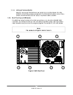
Page 31: ...und AC input is not phase rotation sensitive 5 16 Rear Panel Layout S Models The 802S rear panel is similar to the 802L except these is no SLAVE or INHIBIT BNC connector If a number of units are to be connected in parallel a daisy chain type ribbon cable should be used to connect the supplies together See section 6 4 for more details Note The numbers in Figure 9 refer to Table 5 Figure 9 802S Rear...

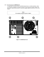
Page 32: ...no interlock terminal unless the CT option is installed If a number of units are to be connected in parallel a daisy chain type ribbon cable should be used to connect the supplies together See section 6 4 for more details Note The numbers in Figure 10 refer to Table 5 L1 L2 L3 N Figure 10 802OEM Rear Panel 1 2 4 5 6 9 ...

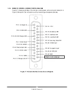
Page 33: ... female Figure 11 Remote Interface Connector and Signals Pin 1 Analog Out Pin 3 Inhibit LED Pin 5 End of Charge LED Pin 7 Inhibit Input Pin 8 HV On Off Pin 9 Peak output volts Pin 10 HV On LED Pin 12 GND Pin 13 Charge current Pin 14 15V Pin 16 Overtemp LED Pin 17 Interlock LED Pin 18 Load fault LED Pin 19 Summary fault LED Pin 20 Inhibit Input Pin 22 Vprogram input Pin 23 HV Off LED Pin 24 GND PIN...

Page 34: ...28 83488001 Revision N Notes ...

Page 35: ...GES MAY POTENTIALLY EXIST FROM THIS POINT FORWARD The power supply should be connected to 3 phase AC power as described in section 4 4 The interlock terminals should be closed either with the supplied shorting link or by an isolated external dry contact Follow the steps below 1 Ensure the output voltage potentiometer is turned fully counter clockwise 2 Turn on the AC power switch the cooling fan s...

Page 36: ...be used to drive a meter displaying peak charging voltage Impedance 10k If the 5V option is installed the voltage level is 0 5V 10 HV ON LED O Open collector through 100 Low impedance when HV output is enabled See Note 1 12 GND Control circuit return Also chassis earth ground 13 Charge current O Uncalibrated Analog of output current waveform Impedance 10k 14 15V O 15V through 100 16 Overtemp LED O...

Page 37: ...sense the remote interface voltage on these signals The user should expect the Active logic level low to be between 2 and 4V If an external pullup resistor is added the Active logic level low voltage will be higher For 802 OEM models a pullup resistor is required to sense voltage levels at these outputs For applications that require logic level inputs the use of an opto isolation device is recomme...

Page 38: ... option is installed 15V OFF Open or Ground ON 6 2 6 Peak Output Volts Pin 9 Peak detector of Analog output voltage waveform Can be used to drive a meter displaying peak charging voltage Signal is 0 10V 1 0 5V if 5V option installed 6 2 7 HV ON LED Pin 10 Open collector Active Low output indicating power supply output is ON Enabled Max rated voltage 60V 100Ω series resistance If the HV ON and HV O...

Page 39: ...ted output voltage 0 5V if 5V option is installed Input impedance 1MΩ 6 2 17 HV Off LED Pin 23 Open collector Active Low output indicating HV output is off disabled Max rated voltage 60V 100Ω series resistance 6 2 18 Ground Pin 24 Control circuit return Also chassis earth ground 6 2 19 12V unfiltered Pin 25 12V unfiltered 6 3 Remote Control Sequence Note The logic levels in the description below a...

Page 40: ...n also be controlled without using the Inhibit signal leaving Pin 7or 20 unconnected and in this case the output current is immediately turned ON when the HV ON signal is activated assuming there are no faults present 6 4 Parallel Operation The 802 series capacitor charging power supplies are constant current sources and can simply be connected in parallel for applications requiring increased powe...

Page 41: ...n control cable is not appropriate and each unit must be individually connected to a remote control system 6 4 1 Parallel system comprising 802L supplies If all of the parallel units are L model supplies then one unit should be operated as the master supply in either local or remote mode The other parallel supplies can be connected to the SLAVE 25 pin D sub connector on the master unit rear panel ...

Page 42: ... in either local or remote mode The other parallel supplies can be connected to the SLAVE 25 pin D sub connector on the master unit rear panel refer to Figure 15 The SLAVE control cable can be a pin to pin ribbon or other cable that is daisy chained to the REMOTE connector on each of the SLAVE supplies To Optional Controller Figure 15 802L and 802S OEM Parallel System control Connections ...

Page 43: ... operated from an external control system The control system should be connected using a pin to pin ribbon or other cable that is daisy chained to the REMOTE connector on each of the 802S OEM supplies in the system A sketch is shown in Figure 16 To Optional Controller Figure 16 Parallel Operation Connections for 802S OEM Supplies ...

Page 44: ...38 83488001 Revision N Notes ...

Page 45: ...ime this manual was produced These documents are continually being improved and expanded so always check for the latest revision on line APP Note 500 Calculating Capacitor Charge Time APP Note 502 Calculating AC Line Currents APP Note 505 Charging units as Continuous Output DC Supplies APP Note 507 Charging Large Load Capacitors APP Note 509 What is Regulation and Repeatability APP Note 513 Power ...

Page 46: ...7 4411 Transportation Emergency Phone 800 424 9300 or 703 527 3887 CHEMTREC Product Technical Information 800 662 4525 MSDS Internet Address http www exxon com http www mobil com SECTION 2 HAZARDS IDENTIFICATION This material is hazardous according to regulatory guidelines see M SDS Section 15 CLASSIFICATION Aspiration toxicant Category 1 LABEL Pictogram Signal Word Danger Hazard Statements H304 M...

Page 47: ...s Substance s or Complex Substance s required for disclosure Name CAS Concentration GHS Hazard Codes 2 6 DI TERT BUTYL P CRESOL 128 37 0 1 5 H400 M factor 1 H410 M factor 1 HYDROTREATED LIGHT NAPHTHENIC DISTILLATE PETROLEUM 64742 53 6 90 100 H304 All concentrations are percent by weight unless material is a gas Gas concentrations are in percent by volume As per paragraph i of 29 CFR 1910 1200 form...

Page 48: ...ammable Limits Approximate volume in air LEL N D UEL N D Autoignition Temperature 315 C 599 F SECTION 6 ACCIDENTAL RELEASE MEASURES NOTIFICATION PROCEDURES In the event of a spill or accidental release notify relevant authorities in accordance with all applicable regulations US regulations require reporting releases of this material to the environment which exceed the applicable reportable quantit...

Page 49: ...nsulted Note Local regulations may prescribe or limit action to be taken ENVIRONMENTAL PRECAUTIONS Large Spills Dike far ahead of liquid spill for later recovery and disposal Prevent entry into waterways sewers basements or confined areas SECTION 7 HANDLING AND STORAGE HANDLING Avoid contact with skin Prevent small spills and leakage to avoid slip hazard Material can accumulate static charges whic...

Page 50: ...ot maintain airborne contaminant concentrations at a level which is adequate to protect worker health an approved respirator may be appropriate Respirator selection use and maintenance must be in accordance with regulatory requirements if applicable Types of respirators to be considered for this material include No special requirements under ordinary conditions of use and with adequate ventilation...

Page 51: ... for safety health and environmental considerations only and may not fully represent product specifications Contact the Supplier for additional information GENERAL INFORMATION Physical State Liquid Color Pale Yellow Odor Characteristic Odor Threshold N D IMPORTANT HEALTH SAFETY AND ENVIRONMENTAL INFORMATION Relative Density at 15 C 0 883 Flammability Solid Gas N A Flash Point Method 145 C 293 F AS...

Page 52: ...leading to discomfort and dermatitis Based on assessment of the components Eye Serious Eye Damage Irritation No end point data for material May cause mild short lasting discomfort to eyes Based on assessment of the components Sensitization Respiratory Sensitization No end point data for material Not expected to be a respiratory sensitizer Skin Sensitization No end point data for material Not expec...

Page 53: ... non specific infiltration of immune cells oil deposition and minimal granuloma formation Not sensitizing in test animals The following ingredients are cited on the lists below None REGULATORY LISTS SEARCHED 1 NTP CARC 3 IARC 1 5 IARC 2B 2 NTP SUS 4 IARC 2A 6 OSHA CARC SECTION 12 ECOLOGICAL INFORMATION The information given is based on data available for the material the components of the material...

Page 54: ...istics of ignitability corrositivity or reactivity and is not formulated with contaminants as determined by the Toxicity Characteristic Leaching Procedure TCLP However used product may be regulated Empty Container Warning Empty Container Warning where applicable Empty containers may contain residue and can be dangerous Do not attempt to refill or clean containers without proper instructions Empty ...

Page 55: ...TK 18 PA RTK 4 OSHA Z 9 TSCA 12b 14 LA RTK 19 RI RTK 5 TSCA 4 10 CA P65 CARC 15 MI 293 Code key CARC Carcinogen REPRO Reproductive SECTION 16 OTHER INFORMATION N D Not determined N A Not applicable KEY TO THE H CODES CONTAINED IN SECTION 3 OF THIS DOCUMENT for information only H304 May be fatal if swallowed and enters airways Aspiration Cat 1 H400 Very toxic to aquatic life Acute Env Tox Cat 1 H41...

Page 56: ...d users Alteration of this document is strictly prohibited Except to the extent required by law re publication or retransmission of this document in whole or in part is not permitted The term ExxonMobil is used for convenience and may include any one or more of ExxonMobil Chemical Company Exxon Mobil Corporation or any affiliates in which they directly or indirectly hold any interest Internal Use ...

Page 57: ......

Page 58: ......

Page 59: ......

Page 60: ......

Page 61: ......

Page 62: ......

Page 63: ......

Page 64: ......

Page 65: ......

Page 66: ......

Page 67: ......

Page 68: ......

Page 69: ......

Page 70: ......

Page 71: ......

Reviews: