p/n 725.0001 REV 1.5
© 2021 TCW Technologies, LLC.
5
6.
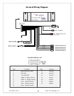
The IBBS unit has a low voltage warning output, pin 3. This pin may be used to drive
an LED indicator or to provide a digital signal to indicate the main input bus is in a low
voltage condition. When the main input bus (connected to pin 5) falls below about 11 volts
this output will drive to a low state. Maximum current sourced into this pin is 25 milliamps.
7.
The IBBS unit has in internal battery monitor connection, pin 2. This pin allows the
voltage state of the internal battery to be monitored with a separate volt meter or an analog
input of a monitor system. This pin will only report internal battery voltage when the unit is
enabled by turning the Back-up Master switch ON. A fully charged battery back will indicate
about 13-14.7 volts on this pin.
Important note: the meter utilized to measure pin 2 must have an input impedance
>100k ohms otherwise it will load down pin 2 and provide an artificially low voltage
reading.
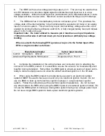
When used with the following EFIS systems wire pin 2 to the Volts2 input of the
EFIS or engine monitor as follows:
8.
Complete the installation of the wiring harness and connector prior to attaching the
connector to the IBBS product. It is essential to ensure the wires do not inadvertently short
together during installation. Remember, the IBBS pack is a back-up source of power and is
ready to deliver output power even when the aircraft electrical system is in the off state.
9.
When using the IBBS product to provide back-up power to an electronic ignition
system it MUST be used to back-up one and only one electronic ignition module. Do not
use one IBBS to back up both electronic ignition modules in a dual electronic ignition
system. Follow the instructions per the electronic ignition manufacture. Do not connect
any other loads to the IBBS when using the IBBS to power an electronic ignition module. Do
not use the IBBS system to back-up a dual ignition system having only a single power input.
Do not use a single IBBS system to back-up two electronic ignition systems.
Manufacturer/model
Volts 2 input location
Garmin G3x system GEA 24
J244, Pin 28
Advanced Flight Systems 5000 series:
Expansion Port Pin 13


