p/n 725.0002 REV 1.4
© 2021 TCW Technologies, LLC.
4
4.
Connect the aircraft wiring according to one of the wiring diagrams shown.
The IBBS must be powered from properly sized circuit breakers or fuses. Ensure the proper
size wire is utilized for the input feed, output supply and ground connection.
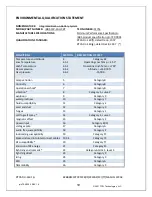
Power Requirements
: The IBBS has multiple power inputs.
Pin 5 receives power for charging the internal battery and bus voltage sensing for the
switching logic within the IBBS unit. Pin 5 must be connected to an aircraft power bus.
When the voltage on pin 5 falls below 11 volts the system automatically transfers the load
current on the output pins to the internal back-up battery source. Pin 5 nominal current draw
is 1.8 amps during charging.
Pin 4 provides power to an internal battery heater system utilized when the battery
temperature is below 0 C°. The nominal current draw is 0.7 amps when the battery
temperature is below 0 C°.
Pins 6,7,8 provide power that is passed-thru the IBBS unit to the loads connected to the
output pins. These pass-thru power connections are optional and only required for systems
that do not have multiple power inputs. These pins can also be used if it is desired to have
redundant power paths feeding the connected loads. These pins are internally wired in
parallel; it is recommended to populate all three pins; join the wires together and feed all of
these inputs from the pass-thru power breaker. Note: these pins do not individually
correspond to any particular output pin (12-15). The pass-thru breaker must be sized for
the load that is connected to the IBBS outputs. The maximum combined load is 10 amps
peak, 5 amps continuous. If Pins 6,7,8 are used they must be connected to the same
source of power as Pin 5.
Output Power connections
:
The IBBS-12v-3ah-CRT has four output pins, Pins 12,13,14,15. These pins provide power
to the connected load. These four wires may be paralleled together for redundancy and
load current sharing. Use 20 awg wire for each pin. The total combined load for all four
pins is 5 amps continuous, 10 amps peak. The output wires of the IBBS system are
protected with a single 10 amp, Mini fuse. This fuse is accessible on the side of the
enclosure.
IMPORTANT NOTE ON CHANGING FUSE:
Disconnect the main product connector before changing the fuse!
Replace fuse with 10 amp, MINI type fuse only
5.
The Back-up Power Master switch must be utilized to turn the back-up battery system
off when not in use. The back-up power master switch gives the pilot the ability to turn the
back-up battery system off. In some installations this may be the only means to shut down
the connected equipment.
6.
The IBBS unit has a low voltage warning output, pin 3. This pin may be used to drive
an LED indicator or to provide a digital signal to indicate the main input bus is in a low


