2800 Laura Lane • Middleton, WI 53562 | 800.288.9383 • | www.tcsbasys.com
33
Introduction
Congratulations on choosing the TCS QD2040C/D series of Ubiquity Cloud Building Managers! This manual covers
versions C and D of the QD2040 Ubiquity Cloud Building Manager. The QD2040C/D series is a compact, versatile network
controller that seamlessly connects with Ubiquity Cloud™ via TCSbus or Modbus.
This manual includes all the information you will need to properly install and set up your QD2040C/D. As most units
come preconfigured, you will most likely only need to read the Installation section of this manual and you can skip the
Configuration section.
However, some customers do order their units without being configured beforehand; for those customers, we include the
comprehensive Configuration section which contains essential information they will need to set up the unit.
If you have any questions regarding your QD2040C/D or your network, contact TCS Technical Support at 800.288.9383,
ext. 2. Our Technical Support Department hours are Monday – Friday, 7:00 a.m. to 7:00 p.m. (CST).
Material List
• QD2040C/D Ubiquity Cloud Site Gateway
• External Power Supply
• Wall Mounting Bracket
•
Two 120 Ω terminating resistors for RS-485 networks
Mounting
The QD2040C/D is designed to be hung on a wall via the mounting screw holes in each unit. It may also be set on a shelf
or table.
If mounting on a wall, do not allow the mounting screws to touch the circuit board inside the enclosure
.
When selecting a location to mount the QD2040C/D, be sure to allow space for cable connections. Locate the QD2040C/D
away from excessive dust, heat sources, moisture or direct sunlight. The ideal environment is a server room. The
temperature of the room should not exceed 77ºF (25ºC); good ventilation is mandatory.
Input Connections
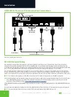
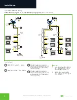
Refer to the
“QD2040C/D Power and Communication Connections” on page 4
for the following input connections:
Power:
Attach the included power supply to the front of the QD2040C/D and insert the power plug into a 120 VAC socket.
Upon connection the unit should power up automatically. If it does not, press the Power button once. The device will beep
to confirm it is powering up (model QD2040D only).
Ethernet:
Connect an Ethernet cable from your network to the Ethernet port labeled Cloud Ethernet 1. Do NOT connect to
Local Ethernet 2, which is only used for administration or as a fail-over Ethernet port (see
“Appendix D: Configuring Local
Management Port as a Failover Port” on page 27
). If you are using a cellular modem, connect the Ethernet cable to the
Ethernet port on the Cellular Modem.
RS-485 Network: Connect an RS-485 network to one of the COM ports.
USB PORT 1-4 (Optional): Connect an RS-485 network via a USB cable to an RS-485 converter (QD1010), or connect a
TCS ZigBee network via a wireless gateway (QW1010).
NOTE:
The remaining ports on the QD2040C/D are unused or reserved for Admin only.
Installation


