


2800 LAURA LANE • MIDDLETON, WI 53562 • (800) 288-9383 • FAX (608) 836-9044 • www.tcsbasys.com
10
the sensor in question. A remote sensor should read 1080
to 1090 ohms at room temperature. The built-in sensor
should read 108 to 109 ohms at room temperature. If any
of the temperatures are still reading slightly high or low, you
can add in a temperature offset (calibration) using Ubiquity
or TCS Insight. In Ubiquity, you can edit the calibration off
-
set for each temperature input (room, discharge, outdoor
air, etc.) on the controller's programming page. For exam
-
ple, if the room temperature is reading 2 degrees high, you
would subtract 2 from the existing offset in the room tem
-
perature calibration offset field and submit the page. In TCS
Insight, the process is similar. Refer to the Calibrate Using
TCS Insight Tech Bulletin # 1019 for details. As a last resort
and only when directed to do so by TCS technical support,
you may be able to use the on-board adjustment pots.
Refer to the Thermostat Sensor Calibration Tech Bulletin #
1005 for details.
Outputs Will Not Shut Off
First check the room temperature and the setpoints and
determine whether the output should be on. There are
delays and minimum on and off times for the fan and
heating and cooling stages. Also, check the service
status menus to verify that the outputs are on. Turning
the system to "off" will instantly turn all outputs off. The
thermostat can be reset by pressing the system switch
button and the service status button simultaneously.
Analog Output Not Working Properly
Check wiring. A separate transformer should be used for
the SZ1063 and SZ1064, and a separate transformer
should be used for the motor(s). Check to make sure
that the analog output is programmed correctly.
Check the Monitoring screens. The Mod Out Screens
will tell you what the SZ1063 and SZ1064 is trying to put
out. Compare this with the actual position on the heating
or cooling device.
Output Operation is not Correct
Check programmed parameters, in particular "Reverse"
and "Direct" acting selections and "Heat" or "Cool"
selections for the analog outputs, and "Offset"and
"Differential" selections and "Delay Times" for the relay
outputs. Check wiring.
LED Description
Six LEDs on the face allow the occupant to view the cur
-
rent operating status of the thermostat.
Rev:0113
C3587_REV2
OCCUPIED
This LED will be lit whenever the unit is operating in the
occupied mode.
HEATING
This LED will be lit when any heat output is operating.
COOLING
This LED will be lit when any cool output is operating.
DATA / PROGRAM
This LED will be lit when the thermostat is within the
programming or clock setup menus. It will blink when the
unit is being accessed by a PC.
SERVICE
This LED will be lit when DI2 is closed.
FAN
This LED will be lit when the fan output is closed.
Limiting Occupant Access
SETPOINT ADJUSTMENT
The occupant may temporarily change the occupied
heating and cooling set/- 5°F by factory default.
This setpoint change will remain until the end of the cur
-
rent occupied period, at which time the program reverts
to the setpoints defined in programming. To change the
range of adjustment allowed, see programming step #22.
OVERRIDE
The occupant has the ability to put the unit into occupied
mode by pressing the override button on the front. By
factory default, the unit will remain in the occupied mode
for 180 minutes. This value may be changed from 0 to
255 minutes in programming step #23.
SETTING CLOCK & SCHEDULE
The ability to set the clock and schedule is allowed by
factory default. An access code may be required as set
in programming step # 49.
PROGRAMMING
The ability to program control parameters is allowed by
factory default. An access code may be required as set
in programming step # 49.
User’s Guide
Inside the hinged door of the thermostat is the
Superstat
TM
User's Guide. This guide is designed to
assist the installer in explaining to the end user how
to operate their new thermostat, as well as serve as a
handy future reference for the end user.
We recommend that the installer fill out the appropriate
pages and explain to the user how the thermostat oper
-
ates, what settings may be changed, and how the time
clock schedules are used.
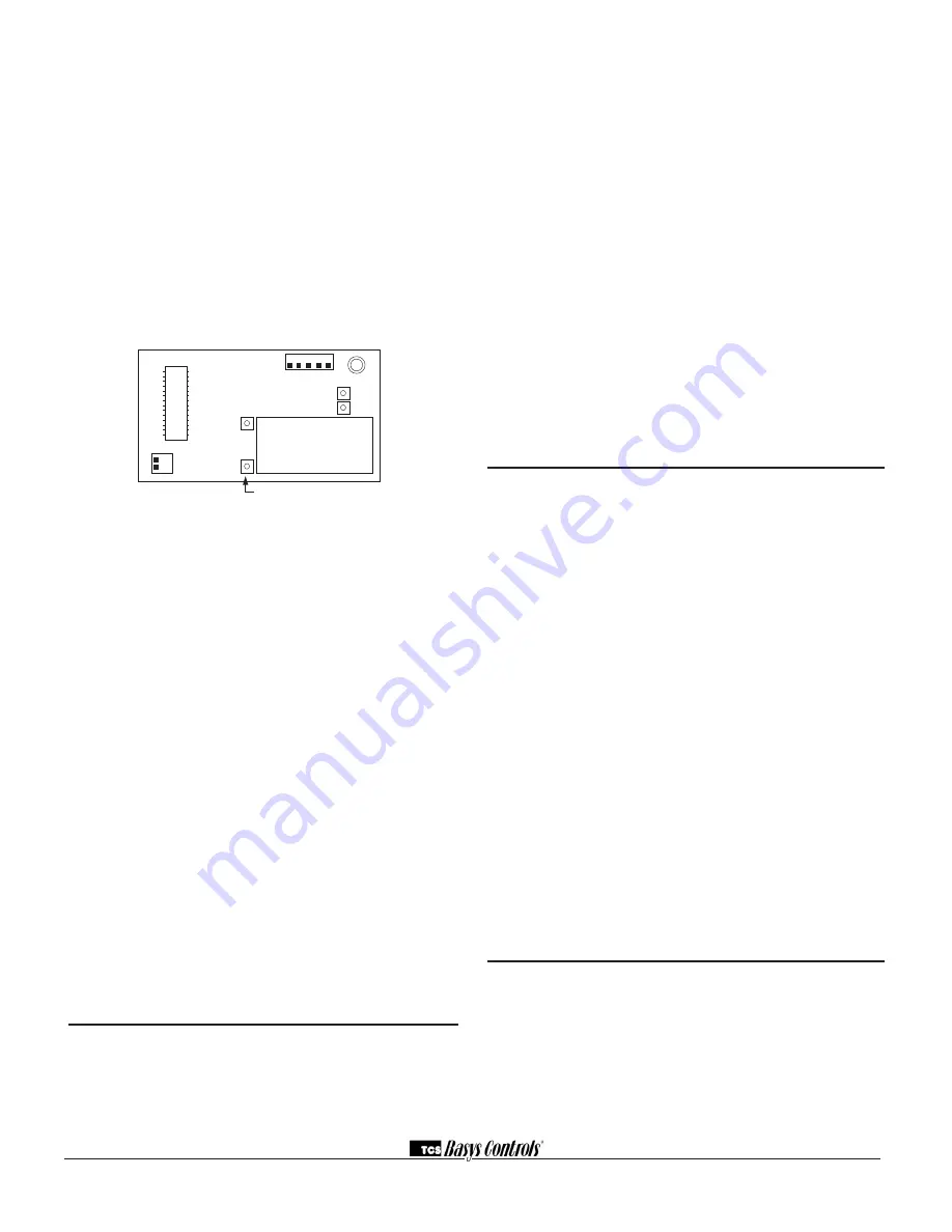
T1
T2
T3
1
2
1 2 3 4 5
adjust display contrast


