


R
2800 LAURA LANE • MIDDLETON, WI 53562 • (800) 288-9383 • FAX (608) 836-9044 • www.tcsbasys.com
12
(SYSTEM SWITCH button), and the unoccupied fan
mode in programming. If the fan is off but the fan LED
is on, check wiring. Short terminals “R” to “G” and see if
the fan comes on. This is a check for a mechanical relay
failure.
Heating or Cooling Does Not Come On
At least one stage of heating is on whenever the heating
LED is on, and at least one stage of cooling is on when-
ever the cooling LED is on. If heating or cooling should
be on but the heating or cooling LED is off:
1. Check the fan and system switch modes.
2. Check the heating and cooling setpoints.
3. Check the room temperature to be sure heating or
cooling should be on.
4. Check the offsets and differentials.
5. If using outdoor air or discharge air high and low lim-
its, check their values to be sure heating or cooling is
allowed.
If heating or cooling is off, but the corresponding SED is
on, check the wiring. Short terminals “R” to “W1”, “W2”
“Y1”,Y2”, or “G” and see if the heating, cooling, or fan
comes on. This is a check for a mechanical relay failure.
Wrong Temperature Display
Initially, verify the wiring connections to check for prob-
lems (poor connections, opens, or shorts). If the tem-
perature is at a minimum or maximum reading, check
that the sensor dipswitch positions are correct as shown
in the Setup section of this document. Also, verify the
resistance reading for the sensor in question. A remote
sensor should read 1080 to 1090 ohms at room temper-
ature. The built-in sensor should read 108 to 109 ohms
at room temperature. If any of the temperatures are still
reading slightly high or low, you can add in a tempera-
ture offset (calibration) using Ubiquity or TCS Insight.
In Ubiquity, you can edit the calibration offset for each
temperature input (room, discharge, outdoor air, etc.) on
the controller's programming page. For example, if the
room temperature is reading 2 degrees high, you would
subtract 2 from the existing offset in the room tempera-
ture calibration offset field and submit the page. In TCS
Insight, the process is similar. Refer to the Calibrate
Using TCS Insight Tech Bulletin # 1019 for details. As
a last resort and only when directed to do so by TCS
technical support, you may be able to use the on-
board adjustment pots. Refer to the Thermostat Sensor
Calibration Tech Bulletin # 1005 for details.
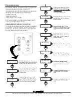
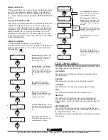
setpoint adjustment limits. Change this to +/-20 °F
(11.1 °C). Press the PROGRAM SETUP button once
more to store the change. Then press the SERVICE
STATUS button once to exit the programming.
4. Press the FAN SWITCH button to access the fan
mode and change the mode to AUTO. Press the
FAN SWITCH button once more to store the change.
Press the SYSTEM SWITCH button to access the
system mode and change the mode to AUTO. Press
the SYSTEM SWITCH button once more to store the
change.
5. Verify that the thermostat is operating in the occupied
mode by making sure that the top LED is lit. If not,
press the OVERRIDE button. The LED should light
up.
6. Take note of the current temperature reading. Press
the WARMER (up) button. The setpoint adjustment
screen should now be showing. Press the WARMER
button until the heating setpoint is greater than the
current temperature by at least five degrees. The fan
will come on. The heating stage(s) will sequence on
after 30 seconds.
7. Press the cooler (down) button until the heating set-
point is one degree less than the current temperature.
The heating stage(s) will sequence off. The fan will
turn off 2 minutes after the last heating stage.
8. Press the cooler button until the cooling setpoint is
less than the current temperature by at least five
degrees. The fan will come on. The cooling stage(s)
will sequence on after 30 seconds.
9. Press the warmer button until the cooling setpoint is
greater than the current temperature by one degree.
The cooling stage(s) will sequence off. The fan will
turn off 2 minutes after the last cooling stage.
10. Go back to programming step #14 and set the set-
point adjust limit back to the desired value. Make any
other changes in programming, clock, and schedule.
Set the fan and system modes to their desired set-
tings.
11. If using remote sensors, verify that the reading is
correct. If not, see
Wrong Temperature Display
in the
Troubleshooting
section.
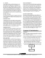
TROUBLESHOOTING
No Display
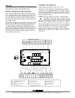
Check for 24 VAC on terminals “+24” and “-24”. Check
ribbon cable connecting the cover to the base for a good
connection.
Fan Does Not Come On
The fan is on whenever the fan LED is on. If the
fan should be on, but the fan LED is off, check
the fan (FAN SWITCH button) and system modes
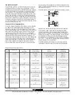
T1
T2
T3
1 2
1 2 3 4 5
adjust display contrast
LIMIT SETPOINT
ADJUST +/-: 5F


