background image

R

2800 LAURA LANE • MIDDLETON, WI 53562 •  (800) 288-9383 • FAX (608) 836-9044 • www.tcsbasys.com

6

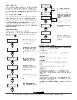
Control Mode Screen.  

Enter if you 

want to control by temperature only (P) 

or add a time factor (P+I).

Time Clock Output Screen.  

Choose 

whether the auxiliary output will be 

OPEN during occupied periods (and 

closed during unoccupied periods) or 

CLOSED during occupied periods (and 

open during unoccupied periods).  


Discharge Air Sensor Function 

Screen.  

Choose whether or not you are 

using a discharge air sensor function. 

To monitor only, select NO. See setup 

instructions for dipswitch settings which 

must also be set.  

Discharge Air Low Limit Screen.  

Enter a discharge air low limit value.  

This screen will not appear if the dis-

charge air sensor function is disabled. 


Discharge Air High Limit Screen.  

Enter a discharge air high limit value.  

This screen will not appear if the dis-

charge air sensor function is disabled.  


Outdoor Air Sensor Function Screen.  

Choose whether or not you are using an 

outdoor air sensor function.  To monitor 

only, select NO. See setup instructions 

for dipswitch settings which must also be 

set.  (Not shown on SZ1022.)


Cooling Lockout Screen.  

Enter an 

outdoor air cooling lockout temperature.  

This screen will not appear if the outdoor 

air sensor function is disabled. (Not 

shown on SZ1022.)


Heating Lockout Screen.  

Enter an 

outdoor air heating lockout temperature.  

This screen will not appear if the outdoor 

air sensor function is disabled. (Not 

shown on SZ1022.) 

DI1 Choice Screen.  

Choose DI1 as 

FAN PROVING or a MONITOR point.  

Select MONITOR if unused.  

SET CONTROL

MODE: 

P+I

program

setup

39.

program

setup

COOLING LOCKOUT

TEMP:              65F

45.

program

setup

ENABLE OUTDOOR

AIR  FUNCT.              YES

44.

DISCHARGE AIR

LOW  LIMIT:                45F

ENABLE DISCHARGE

AIR  FUNCT.            YES

program

setup

41.

program

setup

TIMECLOCK OUTPUT

OCCUPIED=CLOSED

program

setup

40.

DISCHARGE AIR

HIGH LIMIT:           125F

43.

program

setup

42.

program

setup

HEATING LOCKOUT

TEMP:          70F

46.

Heat Stage 2 Differential Screen.  

Enter a differential value for heat stage 

2.  This screen only appears if stage 2 

is enabled.  


Cool Stage 1 Offset  Screen.  

Enter 

an offset value for cool stage 1.  First 

stage is normally 0 offset. 


Cool Stage 1 Differential Screen.  

Enter a differential value for cool stage 

1.  


Cool Stage 2 Offset  Screen.  

Enter 

an offset value for cool stage 2.  This 

screen only appears if stage 2 is 

enabled.    


Cool Stage 2 Differential Screen.  

Enter a differential value for cool stage 

2.  This screen only appears if stage 2 

is enabled.   


Heat or Cool Stage 3 Offset Screen.  

Enter an offset value for heat or cool 

stage 3. (This screen only appears if 

stage 3 is enabled as heat.) 


Heat or Cool Stage 3 Differential 

Screen.  

Enter a differential value for 

heat or cool stage 3. (This screen only 

appears if stage 3 is enabled as heat.) 

Cool Stage 3 or Stage 4 Offset 

Screen.  

Enter an offset value for cool 

stage 3 or stage 4.  This screen only 

appears if this stage is enabled.  (Only 

shown on SZ1035.)

Cool Stage 3 or Stage 4 Differential 

Screen.  

Enter a differential value for 

cool stage 3 or stage 4. This screen 

only appears if this stage is activated. 

(Only shown on SZ1035.)

program

setup

HEAT STAGE 3

OFFSET:              2F

35.

program

setup

COOL STAGE 2

DIFF:              1F

34.

COOL STAGE 1

DIFF:                1F

COOL STAGE 1

OFFSET: 


0F

program

setup

31.

program

setup

HEAT STAGE 2

DIFF:                    1F

program

setup

30.

COOL STAGE 2

OFFSET:                      1F

33.

program

setup

32.

program

setup

HEAT STAGE 3

DIFF:          1F

36.

program

setup

COOL STAGE 3

OFFSET:          2F

37.

program

setup

COOL STAGE 3

DIFF: 

1F

38.

program

setup

DI1 USED FOR:

MONITOR

47.

Summary of Contents for SZ1022

Page 1: ...or limited with the use of an access code Fahrenheit or Celsius temperature display Uses ZigBee protocol IEEE 802 15 4 compliant Self healing plug play mesh network 100mW output at 2 4 GHz 150 to 500...

Page 2: ...install a jumper between the R and 24 terminals The 24 terminal must then be connected to the common side of the unit transformer Wiring The SZ1022 SZ1031 and SZ1035 use standard terminal designation...

Page 3: ...sensor only Using remote room sensor with both discharge and outdoor air sensors SZ1031 and SZ1035 only KEYPAD ACCESS The dipswitches in the thermostat cover shown above must be set in order to lock...

Page 4: ...aud Rate Screen If using a PC to do programming all controllers on a network must be set to the same baud rate Choose between 2 4K 4 8K 9 6K and 19 2K Display Type Screen Choose between FAHRENHEIT and...

Page 5: ...4TH STAGE AS COOL 25 program setup ENABLE THIRD STAGE AS DISABLE 26 program setup HEAT STAGE 1 OFFSET 0F 27 program setup OCCUPIED COOL SETPOINT B 75F 16 program setup OCCUPIED COOL SETPOINT C 75F 17...

Page 6: ...etup ENABLE OUTDOOR AIR FUNCT YES 44 DISCHARGE AIR LOW LIMIT 45F ENABLE DISCHARGE AIR FUNCT YES program setup 41 program setup TIMECLOCK OUTPUT OCCUPIED CLOSED program setup 40 DISCHARGE AIR HIGH LIMI...

Page 7: ...CONDS DI3 USED FOR FILTER SERVICE program setup 50 program setup SET DI2 SETPOINT SHIFT 00F program setup 49 ENABLE SMART RECOVERY NO 52 program setup 51 program setup SET ACCESS CODE 248 55 MON 11 19...

Page 8: ...ed Times Screen Set hours and minutes of start and end times for up to two occupied periods Schedule Announcement Screen Announces the next screen Copy Schedule Screen Indicate whether or not to use t...

Page 9: ...such as with a switch or wind up timer If each occupancy period is about the same theaters meetings another option is to set the DI3 to external override and use the timed override button to put the...

Page 10: ...ment to the building load The offset value is the amount away from the setpoint a stage will turn off By assign ing a stage a value other than zero you anticipate that the residual heat or cooling in...

Page 11: ...35 also have a P I option Without enabling this option stages turn on and off based on temperature vs setpoint alone as described above By enabling this option you allow a time factor to be added This...

Page 12: ...support you may be able to use the on board adjustment pots Refer to the Thermostat Sensor Calibration Tech Bulletin 1005 for details setpoint adjustment limits Change this to 20 F 11 1 C Press the P...

Page 13: ...the override is active and if so how many minutes remain ing service status MON 11 19 01 12 00 AM 72F service status SERVICE STATUS OK 1 service status OUTDOOR AIR TEMP 75F 3 service status DISCHARGE...

Page 14: ...allow the occupant to change the system mode is allowed by factory default To lock out access to system switching see programming step 5 SETTING CLOCK SCHEDULE The ability to set the clock and schedul...

Reviews: