background image

错误

!

未指定书签。


Page 16 of 27 


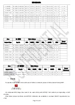
2.4. High Pot. and Insulating Resistance Tests 

 
At  the  end  of  the  process,  a  “High  Voltage”  and  an  “Insulating  Resistance”  tests  are  required  to  fulfil  Safety 

Electrical requirements (CEI 65065). 


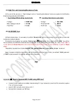
High Voltage Withstanding requirements 


    Insulating Resistance requirements 


“Voltage”   


3500


VAC


“Voltage”     


500 VDC


“Max Leakage Current”     


10 mA


“Threshold Min”  


4M Ω


“Test Time”   


5 sec


“Test Time”   


3 sec


2.5. SHOP-END Test 


At final process stage, it’s necessary to perform “

Reset  shop

” before any packing to leave Factory mode and 

restore User default presets.   

This function is accessible by selecting 

Factory menu 

Reset Shop

”, then pressing RCU “

OK/

►” key. Other 

faster methods via UART/IR commands are available on enclosed SIACP requirements (rev. v5.9) .

While USB3.0 

as the Serial port, 

Reset Shop

 also can close the Serial port function, and it is very necessary to perform 

Reset 

shop

” 

“ResetShop” presets should follow “

MT5531_EU_OOB_MenuSetting_step1_Base_01.doc

” document. 


Note: 

A password might be required in case of Parental Control function is locked, use default “

1234

” password 

or “

0423

” super password to clean-up existing ones if forgotten. 


END 


Appendix


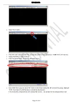
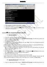
How to upgrade SW FLASH using MTK tool


  Connect UART interface to suitable manufacturing TV input connector (note that PC connector requires 

TVs on “Factory mode”) 

  Launch MTK tool with version above v0.6.7 

  Set right SoC template (ex: MT53xx)   

Summary of Contents for L40S4600/MT31SR-RU

Page 1: ...tion 6 3 Alignment Procedure 7 4 Block diagram 18 5 Scheme Diagram 19 6 Troubleshooting 27 This m anual i s t he l atest at t he t ime of pr inting and doe s not include the modification which may be made after the printing by the constant improvement of product ...

Page 2: ...lectric shock to the person The exclamation point within an equilateral triangle is intended to alert the user to the presence of important operating and maintenance servicing instructions in the literature accompanying the appliance CAUTION Use of controls adjustments or procedures other than those specified herein may result in hazardous radiation exposure CA U T ION RISK RISK OF ELECTRI ELECTRI...

Page 3: ...o impact of any kind Be particularly careful not to damage the picture tube surface 9 Unplug this television set from the wall outlet before cleaning Do not use liquid cleaners or aerosol cleaners Use a damp cloth for cleaning 10 1 Do not place this television set on an unstable cart stand or table The television set may fall causing serious injury to a child or an adult and serious damage to the ...

Page 4: ...ing conductors location of antenna discharge unit connection to grounding electrode and requirements for the grounding electrode 15 2 Note to CATV system installer Only for the television set with CATV reception This reminder is provided to call the CATV system attention to Article 820 40 of the NEC that provides guidelines for proper grounding and in particular specifies that the cable ground sha...

Page 5: ...edurein youroperatinginstructions do not attempt any further adjustment Unplug the set and call your dealer or service technician 22 Whenever the television set is damaged or fails or a distinct change in performance indicates a need for service unplug the set and have it checked by a professional service technician 23 It is normal for some TV sets to make occasional snapping or popping sounds par...

Page 6: ...g Engine High quality scaling engine FHD motion adaptive de interlace Life Time 30000hrs Certification CB Color 1 07B Dithered 10bit DTV Certification CI 1 3 TDT Canal ready SOUND Power Supply AC 100V 240V 50 60Hz Speakers Integrated speakers Bottom side Power Consumption TV on 60W Audio Power Output 8W 2 Power Consumption Standby Less than 0 3W Sound Processing Supports A2 NICAM PAL FM Language E...

Page 7: ...Series Version 1 10 MT31L Low Cost CCFL LED Platform MT31D Low Cost CCFL LED Platform for E3000 ID only MT31B Basic Entry Level LED Platform MT31BT LT DT DVB T2 Chassis LED Platform MT31BS LS DVB S2 Chassis LED Platform MT31DS DVB S2 Chassis LED Platform for E3000 ID only MT31SR Low Cost CCFL LED Platform ...

Page 8: ... 03 18 Delete offsets 0 002 for x and 0 012 for y Add Project White Balance Information v0 40 2013 04 12 Add MAC upgrade method by USB Upgrade MTK Tool for MT31 v0 50 2013 04 18 Mr Christian upgrade information Add PQ engineer Note information Add project White Balance Information Add HDCP upgrade method v0 60 2013 04 23 WB adjust need to fix default G Gain The signal level check has been down in ...

Page 9: ...DVB T C DVB T C DVB T C DVB T C MPEG 2 MPEG 4 DVB T2 DVB S2 DVB S2 DVB T2 HDMI CEC MT31B D 2 MT31L 1 MT31B D 2 MT31L 1 MT31B D 2 MT31L 1 2 MT31B D 2 MT31L 1 MT31B D 2 MT31L 1 480i p 576i p 720p up to 1080i p compliant v1 4a with HDCP VGA 1 1 1 N A 1 1 VGA CMP audio 1 1 1 1 1 1 CMP 1 1 1 1 1 1 YPrPb can support from 480i up to 1080p audio SCART1 N A N A CVBS RGB YC audio Side AV or Back AV N A N A ...

Page 10: ...A N A N A N A N A VGA connector P1000 P1000 P1000 N A P1000 P1000 I2C connector of MEMC module N A N A N A N A N A N A Class Item MT31B MT31L MT31D MT31DS IC Details Position Main SW BIN image NOR 64Mb Flash U702 U702 U702 U702 System Memory Integrated to Flash Integrated to Flash Integrated to Flash Integrated to Flash HDMIx Switch EDID BIN image Embedded to SoC at Firmware On Power Embedded to S...

Page 11: ... product for debugging adjustment and so it s required suitable 0 5V Serial Interface like following snapshot further details are described on below sections VGA as Serial Port USB as Serial Port INFO All tests and measurements mentioned hereafter have to be carried out at a normal mains voltage 220 240 VAC All voltages have to be measured with respect to ground unless otherwise stated All final t...

Page 12: ...ownload Download the latest release SW from below FTP server Link http sw tcl cctv com Username MT31_Factory Password N5246V Folder MT31 B L D includes both TCL THOMSON brand firmware branching subfolders Folder MT31 T2 includes both TCL THOMSON brand firmware branching subfolders Folder MT31 S2 includes both TCL THOMSON brand firmware branching subfolders See Appendix How to upgrade FLASH SW usin...

Page 13: ...ory mode with its VGA port well connected to suitable UART device or an IR emitter device correctly facing up TV see below Product Assembly section 2 0 how to activate Factory key The SoC s RS232 mode is automatically enabled at power on and doesn t require any command initialization frame 0x30 0x30 0x30 0x2E 0x30 0x65 0x30 0x74 0x30 0x0D 0xE2 from host to TV So correctly setup UART parser engine ...

Page 14: ...e well interconnected plug all suitable signals generator to relevant below inputs outputs using respective test patterns format to check picture sound quality Source Test Signal Test Pattern Analog Digital Tuner VHF UHF CATV RF cable generator 2D Movie 1280x720 2D Static Picture 1920x1080 1 Frequency Range full band 2 Standard PAL SECAM 3 DVB T C Satellite Tuner only for MT31BS DiSEqC v1 0 A B C ...

Page 15: ...cho request Headphone RF signal Suitable channel Loud Speakers Enclosures RF signal Suitable channel Picture Video formats and Audio tones can be changed by the factory according to their own standard and broadcasted signals ie 1KHz 3KHz sweep 1 6 AD Calibration Test N A As SoC as built in A D self calibration mechanism there s not any ADC to perform 1 7 DDC EDID T Link Test The E EDID data struct...

Page 16: ...enu Select Picture and press OK key to enter into Picture submenu Scroll down to Contrast item Press the subsequence RCU keys 9 7 3 and 5 In case of FactoryKey is enabled just press RCU Return key to pop up again the Factory menu The status of Factory Key can be changed in Factory Menu Hotkey Press RCU OK key to enter the submenu Press RCU Menu key to go back to the root menu Press RCU key to chan...

Page 17: ...g TCL standard and practices it s required minimum 15min of Warm Up that can be considered as Burn In Additional Aging for White Balance alignment is no more necessary due to consistent Picture Performance with Cloning usage This function is accessible by selecting Factory menu Burning Mode pressing RCU OK key to release disable Burn in mode it s just required to press Menu button from local keybo...

Page 18: ...ustable parameters should be mainly x y coordinates see TCL EU Picture Quality Requirements for FPDs for reference The signal level check has been down in R D Factory should not adjust the scaling Brightness scaling contrast and scaling saturation The White Balance alignment should be performed using a well calibrated and contact less analyzer ex CA310 The analyzer may not touch the screen surface...

Page 19: ...32F33Q9 WE1AWAA 270 280 280 290 315 327 3 0 9 128 128 131 16 0 27 A L32F3393 H3 32F33Q9 WE1BWAA 270 280 280 290 315 327 3 0 9 128 128 131 16 0 27 A 32HW3323 H3 32E33S3 WE1DWAA 270 290 278 302 315 340 3 0 9 123 128 130 16 0 27 A L32E4503 H3 32E45Q9 WE1AWAA 268 286 278 300 314 340 3 0 9 128 128 128 16 0 27 A LT 32HA48U H3 32E45Q9 WE1BWAA 268 286 278 300 314 340 3 0 9 128 128 128 16 0 27 A 32HU5253C ...

Page 20: ...3 WE1NWAA 270 290 280 302 317 341 3 0 9 128 128 128 16 0 27 A L32E3005 H3 32E30X1 WE1AWAA 270 290 278 302 315 340 3 0 9 123 128 130 16 0 27 A 32HW3325 H3 32F15X1 WE1AWAA 270 290 278 302 315 340 3 0 9 123 128 130 16 0 27 A 40FW3324 ID 88 H3 40F15U1 WE1AWAA 265 275 275 287 312 325 3 0 9 120 128 128 16 0 27 A 32HU5253C H3 32E53Q9 WE1DWAA 258 263 268 274 304 312 3 0 9 136 128 134 16 0 27 A 32HU5253CW ...

Page 21: ...00F H3 40F35V3 IRCB0AA 272 292 282 302 316 336 3 0 9 128 128 128 16 0 27 L28E3500 H3 28E35W4 IRCA0AA 270 288 280 298 316 335 3 0 9 128 128 115 16 0 27 L32F3500 ID64 H3 32F35V3 IRCB0AA 268 278 277 290 311 327 3 0 9 127 128 134 16 0 27 L32F3520 ID65 H3 32F35V3 IRCA0AA 268 278 277 290 311 327 3 0 9 127 128 134 16 0 27 L32F3500 ID69 H3 32F35V3 IRCD0AA 258 260 268 272 304 309 3 0 9 128 128 128 16 0 27 ...

Page 22: ...cting Factory menu Reset Shop then pressing RCU OK key Other faster methods via UART IR commands are available on enclosed SIACP requirements rev v5 9 While USB3 0 as the Serial port Reset Shop also can close the Serial port function and it is very necessary to perform Reset shop ResetShop presets should follow MT5531_EU_OOB_MenuSetting_step1_Base_01 doc document Note A password might be required ...

Page 23: ...n Supply the SSB to required voltage Press Upgrade button and appear the below picture Select NOR flash type and press OK button to start downloading the SW and wait the gauge displayed 100 that means the SW has been successfully downloaded In the meanwhile all operations such erasing flash and so are parsed into the debug window script ...

Page 24: ...ce LED is blinking or USB stick starts blinking TV is uploading SW BIN image When reflashing is successful TV should restart automatically after 2min Info If TV doesn t restart and LED is lightening on an error may occurred during flashing check the set PKG file integrity and try again from 1st step Remove USB stick Remember to perform Factory menu Reset ALL or Factory menu Reset Shop and then pre...

Page 25: ...ow to upgrade FLASH SW using OAD A OAD Reflashing Power on TV Set TV to Factory mode enable Factory key and or Burn in mode if necessary Connect RF antenna or whatever air antenna with suitable amplifier from any digital broadcasting system ex DTA 115 Multi Standard VHF UHF Modulator http www dektec com products PCI DTA 115 Play DVB MPEG SSU TS that includes suitable PKG SW image with right preset...

Page 26: ...y UART Connect UART interface to suitable manufacturing TV input connector Launch MTK tool with version above User Tool FlashTo0l exe Open Flash Tool Select menu bar Confing Item Select Flash Download option Click on Flash Download option button and Into option menu Seting Start Address 0x007b0000 Area Length 0x00010000 Select OK Select menu upgrade icon and Load bin File need Hdcp key Select Upgr...

Page 27: ... create a new folder named as XX_ once the CI key is overwritten the matching key file will be moved to this folder Plug USB stick to the TV Go to Factory menu Other Update CI Credential Update From USB and then press RCU OK key The Valid flag should now be enabled turns to Yes Custom Code should displayed TCL and Serial Num field should updated with Key number Remove USB stick Note If unfortunate...

Page 28: ... The Valid flag should now be enabled turns to Yes Custom Code should display TCL and corresponding Serial Number should be updated as well like onto below snapshot Remove UART connection Note If unfortunately the process failed you may need to download new CI key and repeat operation again Appendix How to upgrade MAC address using USB MAC for USB upgrade method as following Create a new folder na...

Page 29: ...te Balance submenu Item Sub item Value Note White Balance Source HDMI VGA DTV PAL SECAM NTSC RGB CMP Select by pressing key Color Temperature Normal Warm Cool Select Tone by pressing key RED Gain 000 255 Set R Gain by pressing key 127 128 for offset GREEN Gain 000 255 Set G Gain by pressing key 127 128 for offset BLUE Gain 000 255 Set B Gain by pressing key 127 128 for offset RED Offset 000 255 Se...

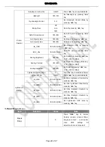
Page 30: ...128 for offset Scaling Contrast 000 255 Set ScCont by pressing key 127 128 for offset Scaling Saturation 000 255 Set ScSat by pressing key 127 128 for offset Lightsensor Setting Page Press key to activate submenu Lightsensor Setting Lightsensor Val On Off Press key to enable disable LS_MAX 000 255 230d Set Max Lightsensor threshold by pressing key LS_MINI 000 255 002d Set Min Lightsensor threshold...

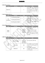
Page 31: ...cy Thailand Press OK key to preload TH Channel Map 8 Power Mode submenu Item Sub item Value Note Power Mode Always On Standby Last Status Select starting sequence by pressing key Always On Force TV to start Standby Force TV to standby Last Status Force TV to standby or to start depanding on latest operation 9 USB Clone Mode submenu Item Sub item Value Note USB Clone USB Clone Mode All ChannelList ...

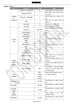
Page 32: ...fo Time Info MTK Version Info ex _002204_4_001_1_002 RCU Info PSU Info Region Info Product S N Info Update MAC address Update from USB Press OK key to copy MAC address from USB Written status Show the writing status NO by default MAC address Show the MAC address NULL by default PC Link Check DO Press OK to check IP address dectection and control MAC DID and UID integrity Auto Standby Off 4 hours 6...

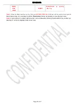
Page 33: ...the VGA port MT31DS MT31SE USB port will be used for Serial port At final process stage it s necessary to perform Reset shop before any packing to leave Factory mode Note2 A quick access to suitable submenu item can be achieved by pressing it prefixed RCU key number ex pressing 9 to directly highlight USB Clone item ...

Page 34: ...06 0R R107 NC 6R8 CD8D 22U NC CD81 10U CD82 0 1U CD80 10U GND GND 35V 220U C109 R191 0R 1 2 4 6 8 12 10 3 5 7 9 11 P102 C116 10U C117 0 1U DDRV 12V DDRV 12V 1 2 3 4 U102 AS1117AD C115 10U R108 56R R109 270R 5V R132 0R R104 33K R105 1K R103 220R R102 330R R190 0R R187 NC 3K3 RD30 39K C136 0 1U C101 10U POWER_ON BL_DIMMING LVDS_PWR_EN1 AVDD1V2 VCCK R133 0R RD62 0R RD63 150K RD61 150K C114 10U R123 0...

Page 35: ...5 63092999 TCLNO DESIGNATION T T GND GND XOUT IF_N IF_P ANT SCL 3V3 SDA GND IF_AGC IF_P AGC ANT_5V I2C_SDA VCC I2C_SCL IF_N Close to MT5531 300mA Close to MT5531 16V NC 220U C200 C201 10U 6 7 1 3 2 4 5 TUN2 6 7 8 1 3 2 4 5 9 TUN1 TU_3V3 CT30 10U CT28 47P CT29 47P RT13 120R RT12 120R GND201 10K RT14 R203 680R 0 047U CT32 NC 47P C237 R205 1K R202 51R R201 51R NC 47P C236 IFAGC IF_AGC_T2 IF IF CT38 2...

Page 36: ... 5 4 3 2 1 U300 RT9711A PR1_IN PR1_IN PB1_IN PB1_IN Y1_IN Y1_IN SCT1_AV_IN GND SCT1_AUL_OUT SCT1_AUR_OUT SCT1_AUR_OUT PB 1 2 P307 1 2 P302 F326 USB_DP_0 USB_DM_0 USB_DP_P0 USB_DM_1 USB_DM_P0 F325 R357 2R2 R356 2R2 F319 F318 R329 2R2 R328 2R2 9 11 10 12 8 7 6 5 2 1 3 4 P303 SCT1_AUR_OUT SCART1L_PA R355 0R SCT1_AV_IN R340 0R YPBPR_R_IN C334 470P C333 470P R303 0R C305 470P 0R R302 1 2 P301 10 4 5 6 ...

Page 37: ...SIGNATION SBU TCLNO DRAWN TCL GND CLOSE TO MT5531 CLOSE TO MT5531 SCART1 Audio Output core power close to chip DDR IO POWER close to chip POWER INTERFACE DDR3 POWER Close to P9 P10 N10 close to Main chip C440 NC 1U C441 NC 1U C406 2U2 DVDD3V3 R426 0R C402 10U R401 1K R400 1K C416 NC 0 1U C415 NC 0 1U C422 0 1U C403 10U DDRV DDRV C436 0 01U C435 0 01U R425 240R C408 1U R424 100R VCCK R422 470R R421...

Page 38: ...U C506 NC 10P C505 NC 10P R529 10K CI_VCC CI_VCC CI_VCC CI_VCC R526 10K CI_DVDD3V3 CI_DVDD3V3 C502 0 1U R525 10K 5V CI_VCC C504 0 1U CI_DVDD3V3 AVDD3V3 R524 47R R523 47R R522 47R R521 47R R520 47R R519 47R R518 47R R517 47R R516 47R CI_VCC R515 47R R514 47R R513 47R R512 47R R511 47R R510 47R R509 47R R508 47R R507 47R R506 47R R505 47R R504 47R R503 47R R500 0R C501 0 1U R502 10K CI_MIVAL_M CI_MC...

Page 39: ... 32 33 34 35 36 37 38 39 40 41 42 43 44 45 46 47 48 49 50 51 P602 LG_DIM_OUT USB_DM_P0 USB_DP_P0 USB_DM_P1 R657 100R OSCL0 R652 NC 100R R653 NC 100R TCON_WP_OUT TCON_WP_OUT T2_RST OSDA0 R656 NC 100R LVDS_VCC C8 D8 C7 D7 A6 B6 C6 D6 C5 D5 A4 B4 C4 D4 C3 D3 A2 B2 E4 F2 C2 E3 C1 D1 F3 D2 F1 U401 MT5531 R651 100R TX_AE0N TX_AE1P TX_AE1N TX_AE2N TX_AE2P TX_AOCKN TX_AOCKP TX_AE3N TX_AE3P C613 0 1U TX_AE...

Page 40: ...ASPDIFO AOMCLK AOBCK AOLRCK AOSDATA0 AOSDATA1 VMID_AADC AVDD33_ADAC AVDD33_AADC AVDD33_CAP DIO CLK HOLD VCC GND WP DO CS GND GND Serial Flash Audio Video MCLK AL1O AR1O FLASH_WP POCE0 PDD6 DVDD3V3 0R R700 VCC_FLASH VGASCL VGASDA VSYNC HSYNC BP SOG GP VGACOM C704 10U C703 10U OSDA0 OSCL0 DVDD3V3 AVDD1V2 3V3SB 3V3SB 5P6 C712 C711 5P6 2K7 R715 R714 2K7 C710 0 1U C706 0 1U 5 6 7 8 4 3 2 1 U702 W25Q64F...

Page 41: ... 10K R834 20K R866 100R R836 560R C806 10U 1 3 2 D801 BAT54A R865 10K R863 300K R864 NC 10M HDMI_2_HPD_CBUS R846 180R R837 33R AVDD3V3 AVDD1V2 C804 0 1U AVDD1V2 C802 0 1U 2 1 4 3 EXC24C L800 HDMI 1 HPD OPWR1_5V HDMI 1 SDA HDMI 1 SCL HDMI_ARC R806 100R HDMI_1_SDA HDMI_1_SCL RX_1_2 R847 82R 2 1 4 3 EXC24C L802 2 1 4 3 EXC24C L801 2 1 4 3 EXC24C L803 HDMI_ARC ARC_OUT C805 2U2 F809 F808 F807 F806 F804...

Page 42: ...7U C17A 2 1 P01A 2 1 P02A C05A 4U7 R01A 100R 48 47 46 45 44 43 42 41 40 39 38 37 36 35 34 33 32 31 30 29 28 27 26 25 24 23 22 21 20 19 18 17 16 15 14 13 11 10 9 8 7 6 5 4 3 2 1 12 U01A TAS5707 C23A 0 47U C21A 0 47U R03A 33R NC R04A 33R L05A 120R 18K2 R07A 10K R11A C19A 1U C20A 0 033U MAIN_POWER 0 033U C25A C18A 0 1U R15A 47K C08A 33P 33P C07A C06A 0 1U C04A 33P NC 470R R12A AVDD3V3 3V3A AVDD3V3 AV...

Page 43: ... 30R R1019 30R R1018 30R C1003 0 01U C1004 0 01U VGASDA VSYNC R1009 100R R1008 100R VGA_HS HSYNC F1004 SOG C1007 0 01U C1009 NC 10P C1008 NC 10P RP VGACOM GP BP C1002 NC 10P C1001 NC 10P C1000 NC 10P R1004 10R R1005 100R VGA TXD C1005 0 01U VGA5V HSYNC VSYNC B G R VGA SCL VGA RXD VGA SDA VGA_5V F1002 F1003 F1005 F1007 R1017 100R F1009 F1008 F1006 F1001 F1010 R1014 10K VGA_5V R1015 10K R1016 100R R...

Page 44: ...LK D_TSDATA0 D_TSDATA1 D_TSDATA2 D_TSDATA3 D_TSDATA4 D_TSDATA5 D_TSDATA7 D_TSDATA6 TSVLD D_TSDATA3 D_TSDATA2 D_TSDATA1 TSVLD TSCLK T2_MOSTART T2_MOSVALA D_TSDATA0 T2_MDO1 T2_MDO2 T2_MDO0 T2_RST OSDA0 T2_MDO2 T2_MDO4 T2_MOSVALA T2_MOCLK T2_MOSTART 1V1_CVDD 3V3_DVDD 1V1_CVDD T2_MDO5 T2_MDO3 OSCL0 T2_MDO1 TSSYNC T2_1V1 TU_3V3 TU_3V3 R1105 47R 1U C1105 47P C1111 C1112 47P R1106 0R R1108 10K 1 4 2 3 X1...

Page 45: ...power board Check every DC DC module Check if main chip Output Pow ON Dim BL ON Signal to power board Check the U401 main IC Peripheral components upgrade main software check whether it connect ground well Check UART LOG Main IC reset signal IIC bus signal Crystal work or not Replace U401 U702 No Only3 3V Yes YES No Yes Yes No Trouble Shooting ...

Page 46: ...picture in all source Check the relevant signal source circuit Check peripheral components of U401 U401 Problem Check the circuit between U401 to panel Check the LVDS connector and T con board and panel Check the row resistor cap and copper of circuit is OK Replace U401 TV AV YPbPr HDMI VGA Trouble Shooting ...

Page 47: ...al sound Abnormal sound in all source Check the relevant signal source circuit Check the waveform of P902 OK Check the status of IIS OK Check Speakers Y Check the status of U900 AMP_VC C mute reset OK Replace U900 Y N N Replace U401 Check the output coupling circuit of U401 OK Y Trouble Shooting ...

Reviews: