background image

5

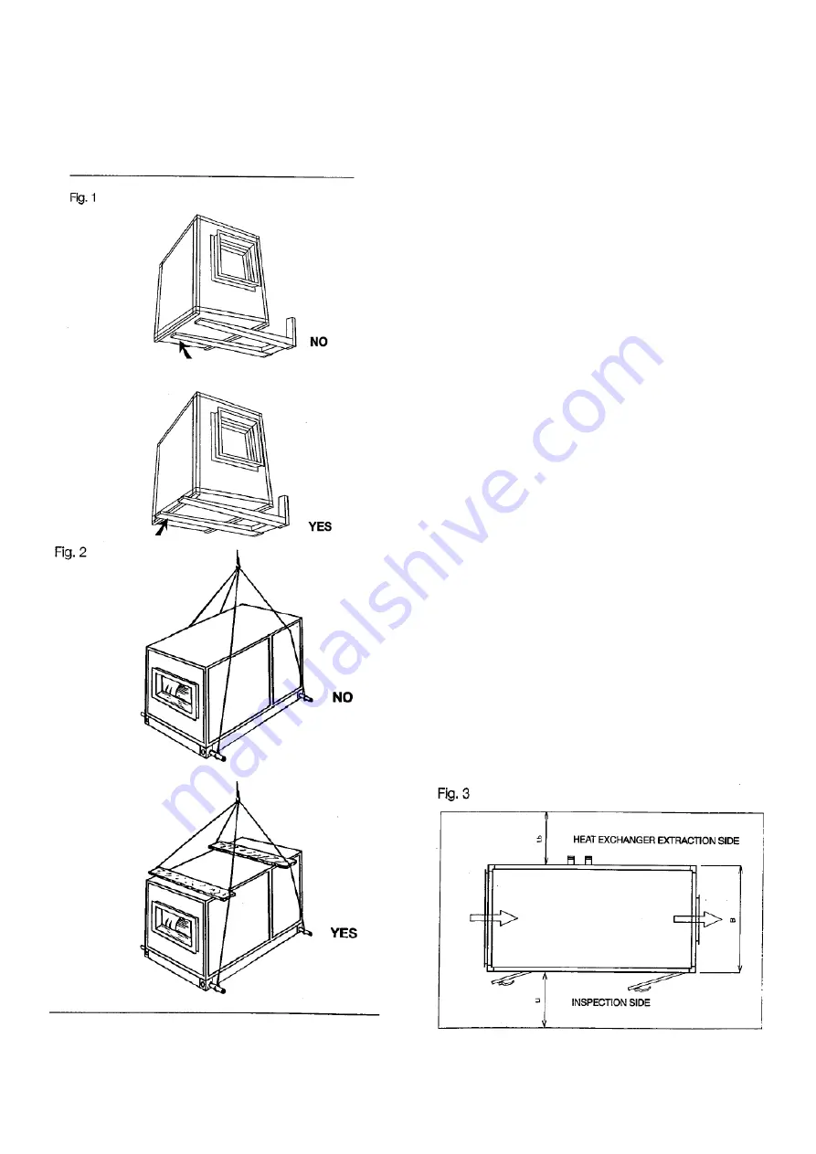
If a crane is used, proceed as shown in the illustration, 
using spacers to protect the structure (fig. 2). 
-  During  transportation,  protect  the  unit  from 
atmospheric  agents.  Special  care  must  be  taken  if  the 
unit  is  supplied  disassembled  or  designed  for  internal 
use. 

3. 

ASSEMBLY ON SITE 

3.1. 

POST-TRANSPORTATION CHECK 

When  the  Air  Treatment  Unit  arrives  on  site,  we 
recommend  you  to  make  a  careful  inspection  of  the 
structure and the component parts of the unit. 
Should  you  come  across  damage  sustained  during 
transportation, you must report it on the freight bill. The 
carrier must immediately tile a report of the accident to 
obtain compensation from the insurance company 

3.2. PRESERVATION ON SITE 

In  order  to  keep  the  Air  Treatment  Unit  in  good  and 
efficient  condition  on  site,  the  following  steps  must  be 
taken first: 
-  Prior  to  installation,  position  the  Unit  and  the 
accessories  in  a  place  affording  the  best  possible 
protection  against  accidental  knocks,  dust  and 
atmospheric agents 
- Carefully cover the inlets and outlets to prevent foreign 
matter from entering the unit and damaging the internal 
components 
- Extract the pre-filters from the Unit and put them in  a 
protected  place  to  preserve  their  filtration  efficiency 
This  is  why  the  superior  efficiency  filters  are  delivered 
packed;  they  must  be  kept  in  their  packages  until  the 
unit is put into service 
-  Check  that  the  hydraulic  connections  are  protected  by 
the  relevant  caps  as  they  were  on  delivery  to  the  TCF 
plant.  lf  they  are  not,  plug  them  in  order  to  protect  the 
exchangers. 

3.3. 

POSITIONING 

3.3.1.   Dimensions of installation room 
The  Air  Treatment  Unit  installation  room  must  be  of 
sufficient  size  to  permit  easy  inspection,  maintenance 
and component replacement. 
Accordingly, 

the 

following 

dimensions 

are 

recommended [fig. 3): 

Summary of Contents for ZAE Series

Page 1: ...1 INSTALLATION OPERATION AND MAINTENANCE MANUAL AIR HANDLING UNITS ZAE SERIES ...

Page 2: ...ging duct section between Unit delivery inlet and obstruction 18 5 3 2 Elbows 19 5 3 3 Control air locks 19 6 MAINTENANCE 20 6 1 FOREWORD 20 6 2 FILTRATION SECTIONS 20 6 2 1 Reconditionable synthetic filters 20 6 2 2 Metal filters 20 6 2 3 Rotary filters 21 6 2 4 Reconditionable bag filters 21 6 2 5 Non reconditionable medium high efficiency filtration sections 21 6 2 5 1 Non reconditionable bag f...

Page 3: ... ryto commissioning The recommendations that follow are intended to ensure continuous operation of the Air Treatment Unit and long machine life The procedures described below should be followed by skilled personnel with a good working knowledge of air conditioning systems engineering and air treatment units even though the unit can be operated by those unfamiliar with air treatment thanks to the m...

Page 4: ...g product compliance with prevailing European Union machine directives 2 2 PACKING The Air Treatment Units are usually supplied as fully assembled monoblocks Only if the customer expressly requests it can the units be broken down into several sections to facilitate transportation and carriage through narrow apertures stairs or corridors Transportation of the machines both monoblock and broken down...

Page 5: ...steps must be taken first Prior to installation position the Unit and the accessories in a place affording the best possible protection against accidental knocks dust and atmospheric agents Carefully cover the inlets and outlets to prevent foreign matter from entering the unit and damaging the internal components Extract the pre filters from the Unit and put them in a protected place to preserve t...

Page 6: ...nctioning of the condensate drains difficulty in opening and closing the inspection doors The horizontal alignment of the support surface must be checked with a SPIRIT LEVEL adjustments may be made using STEEL SHIMS 3 3 3 Vibration damping In order to ensure effective protection against vibrations the Air Treatment Unit must be installed as follows suitable DAMPERS in material designed to withstan...

Page 7: ... assembled parts are perfectly aligned and level fig 8 Fasten the sections together with screws in the holes provided The holes are located on the inside of the corners and in the case of dimensions greater than 1 3 m also in a midway position The screw fastening areas can usually be accessed from the inspection doors Otherwise you must remove the panels next to the area involved Should the Unit b...

Page 8: ...pport the connecting pipes The weight of the pipes must under no circumstances bear down on the manifold 4 2 1 Water exchange In order to ensure an optimum heat exchange you must WASH the heat exchanger before connecting it to the water mains once installed in a workmanlike fashion any air present in the hydraulic circuit must be expelled using the relevant valve To allow easy extraction of the ex...

Page 9: ...ons to prevent the likelihood of rupture at the joint between manifolds and copper pipes In order to ensure correct operation of the thermal expansion valve the bulb of the valve must be in perfect contact with the intake line and fitted on the outside of the air flow so as not to be affected by it Special care must be taken with the SIPHONING of these exchangers to ensure the maximum heat exchang...

Page 10: ...be taken to ensure that the base is level see section 3 3 2 The steam system must be complete with all the necessary regulating filtration and safety devices which must be correctly sized Each heat exchanger must be fitted with a condensate drain which must be oversized to allow drainage of the greater quantity of condensate that is formed during system start up Provision must also be made for the...

Page 11: ...arise in which there is no water in the tank the pump motor would overheat and be irreparably damaged Conversely if there is too much water in the tank an overflow may result leading to flooding of the unit and the installation room 4 3 5 Ultrasonic steam submerged electrodes compressed air humidification For Air Treatment Units with the above listed types of humidification you should consult the ...

Page 12: ...tion of the prefilters located in the relevant counter frames with safety springs or guides The electrical connection and installation instructions for the rotary filtration section are provided in the specific manual provided The instructions for introduction of the reconditionable filtration diaphragm are set out in the maintenance chapter 6 2 3 After removing the filters from the packing in whi...

Page 13: ... motor start up system is obtained by connecting the motor direct to the power supply However this method has limitations due to the high start up current pick UD this type of start up is recommended for power ratings of up to 5 5 KW at which TCF installs 4 pole 220 380 V three phase motors as standard The wiring diagrams are shown in fig 27 4 6 1 2 Connecting with delta star starter If the motor ...

Page 14: ...f the same size but with separate windings 4 6 1 4 Permitted start time With regard to the temperature increase the start up time of a motor may not exceed the value shown in table 1 In the case of repeated starts with unchanging rated power the temperature of the motor must be the same as it was before the first start Therefore in order for the values in the table to be valid it is assumed that t...

Page 15: ...cularly important both during the design and installation phases The sound pressure values of our machines are indicated In our technical catalogues or can be supplied directly by our Technical Department according to the requested air moving characteristics Being therefore aware of the sound emissions produced by the Unit the Designer must make sure that in treated environments maximum values lai...

Page 16: ... check that the motor protection devices are sized for the maximum amperage corresponding to the rated value lf the protection devices are sized for an amperage in excess of the rated value you must make sure that the working range is sufficient 5 2 2 Flowrate check Using an oil or water column pressure gauge or an analogue and or digital gauge check the FLOW RESISTANCE in the various filtration s...

Page 17: ...er operating conditions should be made on the remote control power switches inside the control board using an amperometer clamp Under no circumstances must the measurements be made directly on the motor terminals since this is possible only with the inspection door open a condition that would alter the length of the air circuit and therefore the working point of the fans Descend vertically from th...

Page 18: ...M based on the charts developed by AMCA AIR MOVING AND CONDITIONING ASSOCIATION To calculate the additional flow resistance a graph is used which presents a family of straight lines on logarithmic velocity flow resistance coordinates Each line which is identified by a different letter of the alphabet represents an abnormal situation that determines an additional flow resistance AMCA lists the adve...

Page 19: ...FLOW RESISTANCE VALUES according to the Se sp ratio should the locks be installed on the delivery inlet If the air locks are supplied by TCE consult the SAL air lock technical bulletin Abnormal situations in relation to the reference standard may also occur on the intake and are basically connected with the possible formation of eddies caused by curves in the inlet conduit in conflict with the fan...

Page 20: ...the filtration diaphragm is washed without removing it from the frame if necessary using domestic detergents To avoid damaging the filter the temperature of the water must not exceed 50 C Do not use solvents or caustic soda Let the diaphragm dry by evaporation and refit it only when it is perfectly dry TCF advises you to CHECK THE CONDITION OF THE FILTERS ON A WEEKLY BASIS THE PREFILTERS MUST BE R...

Page 21: ...he aperture uppermost rinse them with a weak jet of warm water 50 C max letting the impurities run out at the bottom through the filtration diaphragm let the filters dry thoroughly by evaporation before refitting them Do not use air jets to dry them In this way the filters can be cleaned 2 3 times after which the filter s characteristics will be compromised and it will have to be replaced 6 2 5 No...

Page 22: ...freezing with the arrival of winter For this purpose TCF recommends the following steps In the case of prolonged idleness of the heat exchanger circuits they should be completed drained Where an anti freeze system based on heating elements is provided to protect the exchanger make sure that the control board is constantly powered up On systems operating with anti freeze check its efficiency and to...

Page 23: ...ows stop the electrical pump cut off the water feed using the relevant gate let the block dry completely keeping the fan in operation remove the frame housing the block by undoing the securing screws and lift it out of the unit through the inspection door extract the fouled block from the housing and replace it with another of the same size Take care with the direction of fluid flow the water whic...

Page 24: ...ed with grease nipples require periodic lubrication The greasing intervals under normal operating conditions are shown in Table 11 TABLE 10 Greasing of motor bearing NOTE The bearings must be greased more frequently in harsh operating conditions 6 5 3 Drive In order to ensure optimum drive efficiency and to avoid damaging the fan motor unit the drive must be kept in perfect working order The follo...

Page 25: ... case of drives with several belts the belts must be replaced at the same time This means that there must not be belts presenting different states of wear in the same drive system the number of belts must always match the number of races in this type of drive system the belt slack must be on the same side as shown in Hg 40 before they are tensioned 6 6 Heat recuperator 6 6 1 Crossover flow static ...

Page 26: ... rate This is the result of an uncontrolled increase in resistance in the air moving circuit which alters the fan s operating point The most frequent causes are excessively clogged filters formation of frost or ice on the front surface of the prefilters in particularly damp and cold climates on Units operating entirely with external air blockage of the intake grille s especially external air intak...

Page 27: ...s working life 7 SAFETY 7 1 SAFETY RELATED FEATURES OF AIR TREATMENT UNIT TCF Srl has fitted its Air Treatment Units with every possible safety feature to prevent accidents especially during start up and maintenance Some of these SAFETY FEATURES are listed below INSPECTION DOORS THAT CAN ONLY BE OPENED WITH A KEY are installed in the sections housing rotating parts and drives the GRATES and HOUSIN...

Page 28: ...ano di Granarolo E BO Declares that the following products AIR HANDLING UNIT Mod ZAE Customer Reference Order n Construction year is in compliance with the following Directives 2004 108 CE 2006 42 CE 91 368 CEE 93 68 CEE 2006 95 CE IT IS NECESSARY HOWEVER TO VERIFY THAT THE INSTALLATION AND THE DRIVE ARE CARRY OUT TO YOU CORRECTLY AND IN THE RESPECT OF DIRECTIVES EMC 2004 108 CE AND 2006 42 CE and...

Page 29: ...hould be sent prepaid to our headquarters and the replacement will be sent carriage forward Please note too that the warranty does not include the services of our personnel for the replacement of the part on site this cost is entirely for the installer s account On receipt of the returned material deemed to be defective an inspection will be carried out to establish whether the part reveals abnorm...

Page 30: ...30 ...

Reviews: