background image


Obtaining UpCon status information

UpCon English Manual (2014-10-07) 46

Please note that the LEDs on the front of a Up-
Con will display basic status information as long 
as the device is powered – see “Front panel indi-
cators” on page 24
.

Additional status information can be obtained 
using TC Icon, where you can also define how 
certain error states should be indicated on the 
device.

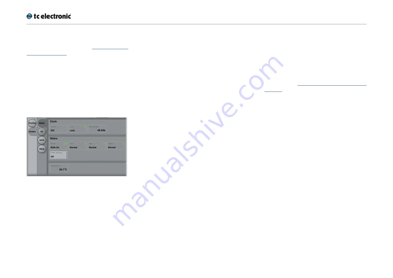
To display status information about UpCon, go to 
Frame / System / Status.

Fig. 24.: UpCon (SDI) Status page

This page will display the following status infor-
mation:

Clock section

Source indicator

Indicates the source of the clock signal UpCon is 
currently following.

Lock indicator

Indicates wether synchronization has been 
achieved. If no synchronization has been 
achieved, a red LED will be shown in this field.

Nominal Rate indicator

Shows the detected sample rate of the signal 
UpCon is synced to.

Status section

Power indicator

Displays the current state of the UpCon power 
supplies.

A power supply failure may be indicated as de-
scribed under “Power Warning parameter” on 
page 46.

Power Warning parameter

A failing supply is 

always

 indicated by a red LED 

on the front panel of the device. TC Icon can also 
indicate a failing power supply, depending on the 
setting of the “Power Warning” parameter.

“Off” setting

A failing power supply is not reported in the Icon 
remote app.

“Warning” setting

A failing power supply is indicated by a 

yellow


“Power” label in the respective UpCon Frame in-
dicator, and a yellow LED will be shown on the 
Frame tab when it is selected.

“Error” setting

A failing power supply is indicated by a 

red


“Power” label in the respective UpCon Frame 
indicator, and a red LED will be shown on the 
Frame tab when it is selected.

Summary of Contents for UpCon

Page 1: ...English Manual UpCon Product UpCon Product firmware version Frame software 1 8 00 Document English Manual Document version date 2014 10 07...

Page 2: ...onnectors 27 Setting up UpCon 31 Networking basics and troubleshooting 32 Quick Setup 35 Updating UpCon software 36 Basic operation 37 Introduction 38 Basic TC Icon operation 38 Faders 39 On screen ke...

Page 3: ...UpCon algorithm Auto page 96 Appendix 1 Links and additional information 98 Support resources 99 TC Electronic on 99 TC HD resources 99 Product related information 100 Extending your product s capabil...

Page 4: ...Important safety instructions UpCon English Manual 2014 10 07 1 Important safety instructions...

Page 5: ...re they exit from the apparatus 11 Only use attachments accessories specified by the manufacturer 12 Use only with the cart stand tripod bracket or table specified by the man ufacturer or sold with th...

Page 6: ...d your authority to operate this equipment To completely disconnect from AC mains disconnect the power supply cord from the AC receptacle The mains plug of the power supply shall re main readily opera...

Page 7: ...pment off and on the user is encouraged to try to correct the interference by one or more of the following measures Reorient or relocate the receiving antenna Increase the separation between the equip...

Page 8: ...About this manual UpCon English Manual 2014 10 07 5 About this manual...

Page 9: ...all connections to external equipment as described in Setting up UpCon on page 31 In the subsequent sections of the manual we assume that all connections are made correctly and that you are familiar w...

Page 10: ...Before you get started UpCon English Manual 2014 10 07 7 Before you get started...

Page 11: ...h Manual 2014 10 07 8 Register your product Please register this product so we can inform you about updates and other product related news To register your product please go to tcelectronic com suppor...

Page 12: ...Unpacking and setup UpCon English Manual 2014 10 07 9 Unpacking and setup...

Page 13: ...Depending on the configuration you have pur chased the box should contain the following items 1 UpCon unit 2 power cables 1 USB stick containing the TC Icon software the UpCon software this manual in...

Page 14: ...Software TC Icon and UpCon firmware UpCon English Manual 2014 10 07 11 Software TC Icon and UpCon firmware...

Page 15: ...ng TC Icon software is described in this section of the UpCon manual 2 TC UpCon firmware UpCon firmware is the software installed on every UpCon Every UpCon comes pre installed with the most current f...

Page 16: ...support page look for TC Icon software and click the button rep resenting the latest version of the TC Icon software for Microsoft Windows Depending on your browser type and con figuration a dialog ma...

Page 17: ...icon TC Icon will try to establish connections to all connected TC devices on a local network in cluding your UpCon If a connection cannot be established please refer to Networking basics and trouble...

Page 18: ...may be shown asking you what you want to do with this file Choose Save The software will be downloaded to your browser s default download location Usually this is the Downloads folder for your user a...

Page 19: ...trouble shooting on page 32 If you experience technical problems during software download or installation please ask a person with administrator privileges on this com puter for assistance Updating TC...

Page 20: ...UpCon An introduction UpCon English Manual 2014 10 07 17 UpCon An introduction...

Page 21: ...pens at the end listener s TV set This is essential to broad casters that generally transmit 5 1 signals but receive commercials in stereo or air newscasts relying on signals coming in from around the...

Page 22: ...UpCon Basic concepts and operation UpCon English Manual 2014 10 07 19 UpCon Basic concepts and operation...

Page 23: ...ms that may include many net worked TC signal processors Hardware versions UpCon is available in five different hardware versions UpCon SDI with one two or three du al engine processing cards installe...

Page 24: ...Con features one of the most complex and intelligent technologies we have ever made It is based on the TC developed DICE core with its JET technology which has been further re fined to deliver importa...

Page 25: ...ereo you can always have 5 1 and stereo on the outputs Artifact free Artifact free crossfade be tween bypass and upconversion GPIO and SDI metadata Engage format conversion using GPIO or SDI metadata...

Page 26: ...UpConstatus indicators and ports UpCon English Manual 2014 10 07 23 UpCon status indicators and ports...

Page 27: ...I cards Additional status information can be displayed using TC Icon software see Obtaining UpCon status information on page 45 PSU 1 and PSU 2 LEDs The PSU 1 and PSU 2 LEDs indicate the status of the...

Page 28: ...a description of all Sync states see AES In put State indicators on page 53 LED color indication Status Off Startup no lock achieved lock status unknown Green A clock signal has been de tected at the...

Page 29: ...r to reset Ethernet communication between UpCon and a computer when a communication error has occurred Resetting the IP address of a UpCon unit It may be necessary to reset the IP address of a UpCon u...

Page 30: ...ams Back panel connectors Fig 16 UpCon back panel connectors SDI version PSU 2 x UpCon has two C13 type power inlet sockets The dual power inlets provide extended opera tional security and stability T...

Page 31: ...nnect the upstream SDI device to an SDI In socket on UpCon Use a coaxial cable with BNC connectors with a nominal impedance of 75 Ohms Connecting multiple 3G cards If you are using a UpCon with two or...

Page 32: ...alanced AES version of UpCon has 8 AES 3id Out ports on BNC connectors with one channel pair per connector The SDI versions of UpCon have no AES Out ports Fig 17 UpCon AES unbalanced version back pane...

Page 33: ...hannels of unbalanced AES I O and by default the first 8 channels are active Should you need even more channels you can purchase a separate license for activating chan nels 9 16 See Extending your pro...

Page 34: ...Setting up UpCon UpCon English Manual 2014 10 07 31 Setting up UpCon...

Page 35: ...re will detect a Up Con out of the box without problems However if it doesn t there is most likely a subnet issue or an IP address conflict In this case please refer to the following sections Subnet m...

Page 36: ...P address of your computer depends on the operating system you are using and your account privileges In case of doubt please consult your company s network administrator To find and change the TCP IP...

Page 37: ...case of an IP address conflict that keeps you from accessing UpCon in the first place you need to change your computer s IP first as de scribed in the previous section Launch the TC Icon software on y...

Page 38: ...ple setup as illus trated below Ethernet connection Requirements for this setup are A UpCon A CAT5 Ethernet cable A computer equipped with an Ethernet adapt er running Microsoft Windows or Mac OS X an...

Page 39: ...ion are supplied with your Up Con However from time to time software updates are made available by TC containing both bug fixes and new features Please download and install the most current version of...

Page 40: ...Basic operation UpCon English Manual 2014 10 07 37 Basic operation...

Page 41: ...hooting on page 32 Basic TC Icon operation The TC Icon software interface has been opti mized for use in real time situations in broadcast and post production environments which usual ly are very diff...

Page 42: ...erate your UpCon efficiently There are six on screen faders You can change the position of the faders or hide them completely see UI page on page 85 The name of the parameter that a fader is currently...

Page 43: ...p 1 means that you have selected the predefined Fader Group 1 for Engine 1 To set up the User Fader Group Select the tab of an Engine on the top edge of the TC Icon software window Use the arrow butto...

Page 44: ...here text input is required When you access one of these functions an on screen keyboard will be displayed Fig 23 TC Icon software On screen keyboard While they keyboard is being displayed you can eit...

Page 45: ...Accessing UpCon UpCon English Manual 2014 10 07 42 Accessing UpCon...

Page 46: ...ight on screen slots locations If a connected device is not detected please refer to Networking basics and trouble shooting on page 32 Click the icon representing the UpCon to ac cess it Operating mul...

Page 47: ...our setup when devices are powered up or down or if there are connection errors these may not be detected immediately In this case you should scan the network again To scan a network for devices In th...

Page 48: ...Obtaining UpCon status information UpCon English Manual 2014 10 07 45 Obtaining UpCon status information...

Page 49: ...D will be shown in this field Nominal Rate indicator Shows the detected sample rate of the signal UpCon is synced to Status section Power indicator Displays the current state of the UpCon power suppli...

Page 50: ...may need to identify one specific unit quickly To do so select the respec tive Frame using TC Icon software and then use the Frame Identification parameter to have that Frame identify itself with blin...

Page 51: ...Obtaining UpCon status information UpCon English Manual 2014 10 07 48 Temperature indicator Shows the current internal temperature of Up Con in degrees Celsius...

Page 52: ...Setting up audio and syncing UpCon English Manual 2014 10 07 49 Setting up audio and syncing...

Page 53: ...Con is not locking to any incoming SDI stream the For mat indicator field will read N A Available Groups indicators SDI with embedded audio carries up to 16 chan nels of audio divided into four groups...

Page 54: ...ere selected using the Audio Groups selector This is the default setting which is also used when Advanced SDI mode has not been activated Settings Groups 1 2 Groups 3 4 Groups 1 3 Groups 1 4 Groups 2...

Page 55: ...ams differ UpCon will not be able to de embed and process au dio Stream 1 setting The UpCon will de embed and embed two of the up to four available audio groups in stream 1 This is the default setting...

Page 56: ...ut that UpCon is set to lock to or if the incoming sample rate is outside the legal range 48 kHz 1 7 1 3 and the Clock Fallback is set to Freewheel Internal yellow LED Warning Internal is displayed wh...

Page 57: ...48 kHz Use the Clock Master parameter to set whether UpCon should be referencing an incoming ex ternal clock source or an internal crystal running at 48 kHz External reference is mandatory in a broad...

Page 58: ...Con unprocessed Setting up audio dithering To set up audio dithering go to Frame Sys tem I O Dither Fig 28 System I O Dither page Use the Dither page to set up if and how audio signals should be dithe...

Page 59: ...UpCon remote control UpCon English Manual 2014 10 07 56 UpCon remote control...

Page 60: ...ee Library Recall page on page 69 Please not that the Icon user interface is locked when GPI is used for control GPI button Use this button to enable GPI 1 input for User Scene Recall An Enable button...

Page 61: ...hows the current audio processing details no matter if GPI or SDI metadata is used for control Normal display If Normal is displayed audio processing is not remote controlled and the unit works as spe...

Page 62: ...nk using the Scene Bank parameter 7 Presets setting Select one of seven Presets using GPI1 Select the Preset Bank using the Scene Bank parameter For a description of the Idle state see Idle state on p...

Page 63: ...the setup of GPI control display GPI 1 is not enabled or the incoming voltage is outside of valid windows Check the device s GPI calibration the incoming voltage and the general external GPI setup Idl...

Page 64: ...age Main the For mat Conv parameter will be greyed out and a blue LED indicates that it is being remote con trolled Engine parameter Settings E1 E2 E1 E2 Use the Engine parameter to specify which En g...

Page 65: ...four GP inputs To calibrate a GPI input click the respective Cali brate button and follow the on screen instruc tions Setting up GPO To set up GPO go to the Frame System Re mote GPO page Fig 30 UpCon...

Page 66: ...ent is stereo and the optional C LFE Ls and Rs channels are used for intercom signals the Ch Mode 2 0 approach will allow you to force Up Con to disregard the incoming optional C LFE Ls and Rs channel...

Page 67: ...15 16 Use this parameter to specify the audio chan nel pair in the SDI stream from which metadata should be read SDID background information SMPTE2020 metadata are divided into audio programs that e...

Page 68: ...r is described here In the messages listed below Ex specifies what Engines are affected by the remote control and this relates to the Engines parameter see Engines parameter on page 64 Normal display...

Page 69: ...Recalling storing and deleting settings UpCon English Manual 2014 10 07 66 Recalling storing and deleting settings...

Page 70: ...tal recall All the settings that make up a Scene are called a Scene preset Recalling Loading storing saving and deleting Scene Presets is covered in the Recalling stor ing and deleting settings on pag...

Page 71: ...ld either 50 Scene presets or 50 Routing presets or 100 Engine presetsFactory presets vs user presets When recalling presets you will see that there are two categories of presets Factory presets and U...

Page 72: ...recall a Routing preset E ngine 1 or E ngine 2 to recall an En gine preset and use it for the currently se lected Engine Select between Factory and User preset groups by clicking the Factory or User...

Page 73: ...ry Recall page on page 69 Naming Presets All user preset types can be re named To rename a preset On the Store page select the preset that you want to rename Click the Name button An on screen keyboar...

Page 74: ...he unit while renaming presets Please note that even when renaming presets or adding information as described above the faders for the previously accessed page are still available and operational This...

Page 75: ...bpage for the setting type you want to delete Scene Route E ngine 1 or E ngine 2 Select a User preset group There are 8 User preset groups with each group holding up to 8 presets Select a preset in th...

Page 76: ...ge Select the subpage for the setting type you want to copy Scene to copy Scene presets Route to copy Routing presets Engine to copy Engine presets To copy from a Bank to a file on disk Select From Ba...

Page 77: ...Updating UpCon firmware UpCon English Manual 2014 10 07 74 Updating UpCon firmware...

Page 78: ...e firmware of your UpCon re quires a computer with the TC Icon software installed In TC Icon you can select a previously down loaded UpCon firmware file with a tca suffix and apply it to the currently...

Page 79: ...pending on your browser type and con figuration a dialog may be shown asking you what you want to do with this file Choose Save The software will be downloaded to your browser s default download locat...

Page 80: ...Assuming that your hard disk drive has the letter c you extracted the downloaded tca file to the folder UC on the drive root see pre vious steps the correct path would be C UC Click Enter You will be...

Page 81: ...file has been extracted you will see a tca file in the Finder In the next steps you will select this tca file in the TC Icon software to transfer it to UpCon For the first example we will assume that...

Page 82: ...eturned to the previ ous screen The name of the tca file you downloaded should now be displayed right under the Common Software Update Folder field If you want to make sure you have selected the corre...

Page 83: ...pdate Folder would be Volumes DAW2 UpCon_updates For the remaining steps see Example 1 Please note that a folder may contain mul tiple tca files which will be shown on the Frame System Setup Update pa...

Page 84: ...Icon Setup UpCon English Manual 2014 10 07 81 Icon Setup...

Page 85: ...bol in the upper left corner of the window see TC Icon modes Base and Device operation on page 39 In Base Mode you will see the Select Auto and Setup tabs on the upper edge of the TC Icon window Selec...

Page 86: ...ter problems when detecting con nected devices please refer to Networking ba sics and troubleshooting on page 32 Assigning devices to the available slots You need to assign a device to a slot of the T...

Page 87: ...ellow warning in dicators will remain lit until the user presses Re set Clip button This feature ensures that clock errors or clippings do not go unnoticed Lock Device UI button Click the Lock Device...

Page 88: ...should be shown Three op tions are available Changes on this page will take effect next time you open the TC Icon soft ware Faders at bottom setting Faders will be positioned right below the main inte...

Page 89: ...tly selected User scheme You can change the colors used for Background Icon Panel Front Icon Panel Back Device Panel Front Device Panel Back User Interface Text We suggest changing these colors under...

Page 90: ...The UpCon algorithm UpCon English Manual 2014 10 07 87 The UpCon algorithm...

Page 91: ...nal falls back from true 5 1 to stereo it seamlessly crossfades into a convincing 5 1 surround upconversion without adding any interruptions or artifacts Detection does not require metadata or GPIs to...

Page 92: ...setting UpCon is automatically enabled when the input format is stereo If both inputs are active priority is given to the 5 1 input Aux Priority setting When 5 1 and Stereo signals are fed to differen...

Page 93: ...ormat Convert parame ter on UpCon s Main page to Downmix the Gain Center parameter can be used to apply a static gain to the Center channel before delay and true peak limiting If the processed input s...

Page 94: ...ter and Right Front pa rameters to adjust the levels of these channels when upconversion is active After tuning other upconversion parameters ad just these parameters so that loudness before and after...

Page 95: ...se a setting between 20 and 24 dBFS For music use a setting between 14 and 20 dBFS C Contour Style parameter Use the C Contour Style parameter for Center channel extraction L R Process parameter Use t...

Page 96: ...se the Surround Spectrum parameter to set the frequency response for surround channel extraction For best results set this parameter in combina tion with the surround channel Gain parameters on the Le...

Page 97: ...udio quality defining factor the so called headroom Analog TV only had around 10 dB of headroom but DTV should have at least 15 16 dB of headroom for a chance of conveying audio of a decent quality Ra...

Page 98: ...or Universal for all round adaptive settings For AC3 delivery use the AC3 Codec Profile setting For all settings except for AC3 Codec the true peak threshold is the same for all channels For AC3 Code...

Page 99: ...them UpCon assumes that a 5 1 signal is available and cross fades into 5 1 bypass Note that this automation mode gives priority to a 5 1 signal and that outputs are never muted When no 5 1 signal is p...

Page 100: ...The UpCon algorithm UpCon English Manual 2014 10 07 97...

Page 101: ...Appendix 1 Links and additional information UpCon English Manual 2014 10 07 98 Appendix 1 Links and additional information...

Page 102: ...TC Electronic all product manuals tcelectronic com support manuals TC Electronic user forum forum tcelectronic com TC Electronic on the web tcelectronic com Facebook facebook com tcelectronic Google P...

Page 103: ...can be extended by purchasing optional licenses listed below To learn where to obtain demo versions or buy licenses to extend your TC HD product please go to tcelectronic com where to buy 16 Channel...

Page 104: ...Appendix 2 UpCon GPI O page UpCon English Manual 2014 10 07 101 Appendix 2 UpCon GPI O page...

Page 105: ...3 power supply When nothing is connected to the GPI input the input voltage therefore is 3V3V A resistor net work can be used to pull down the voltage as suggested in Fig 3 4 GPI installation Selectio...

Page 106: ...los clos 1 of 8 1 1 000 idle 3 20 3 30 3 30 open open open 2 0 826 2 63 2 73 2 83 clos open open 3 0 689 2 18 2 28 2 38 open clos open 4 0 602 1 93 1 99 2 05 clos clos open 5 0 548 1 75 1 81 1 87 open...

Page 107: ...Technical specifications UpCon English Manual 2014 10 07 104 Technical specifications...

Page 108: ...d max 10 4 lbs 4 7 kg Mains voltage 100 to 240 VAC 50 60 Hz auto select Power supply function Dual Power Supply Redundancy Fan Dual Fan Redundancy Power consumption UpCon with 1 card 14 W typ UpCon ex...

Page 109: ...nnels processed 8 in 8 out per card 16 in 16 out optional for AES Audio format configuration 2 5 1 2 2 5 1 2 2 5 1 5 1 5 1 Audio processing delay 0 15 ms Adjustable online delay 0 10 sec per audio cha...

Page 110: ...dards SMPTE 259M 292M 424M 425M Audio input output selection SDI group 1 2 3 4 3G stream 1 3G stream 2 Interface function de embed embed Synchronous bit transparent Input return loss Typ 17 dB 1 5 GHz...

Page 111: ...ision 30 PPM External Sample Rates 48 kHz 1 7 1 3 Audio in to out delay 0 85 ms Number of audio channels processed 8 in 8 out 16 in 16 out Interface function Synchronous bit transparent Jitter Rejecti...

Page 112: ...on 30 PPM External Sample Rates 48 kHz 1 7 1 3 Audio in to out delay 0 85 ms Number of audio channels processed 8 in 8 out 16 in 16 out Interface function Synchronous bit transparent Jitter Rejection...

Page 113: ...Interface GPI control inputs D SUB 4 multi state multi function 0 V to 3 3 V DC sensing GPO output D SUB 2 relays floating 200 mA 24 V AC DC max Output voltage D SUB 3 3 V DC 100 mA current limited Et...

Page 114: ...Technical specifications UpCon English Manual 2014 10 07 111...

Reviews: