TC Electronic SYSTEM 6000 MKII Operation Manual Download Page 38

38

ICON SETUP PAGE

Icon User Interface

Go to the Select & Setup pages pressing the TC Icon

key in the upper left corner.
Press SETUP (upper tab) and UI (side tab) to enter the

setup page for the TC Icon display.

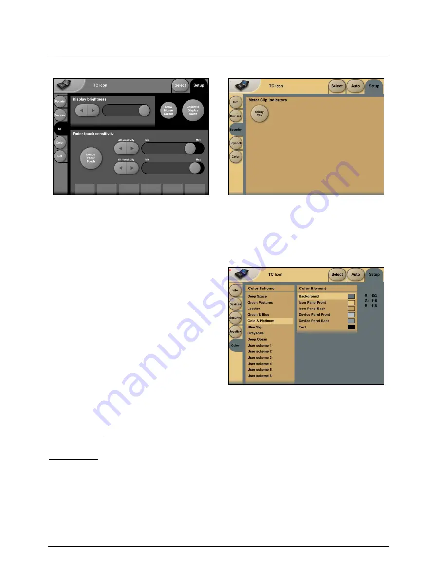
TC Icon Display Parameters

In this display you setup various parameters regarding the

appearance of the display as well as the Fader Touch

Sensitivity.

Display Brightness

Adjust the brightness of the display using either the 

Arrow

cursors or simply drag the “

Adjust

handle”.

Show Mouse Cursor

Press to show mouse/pointer position.

Calibrate Display Touch

For optimal performance the Touch Screen will at times

need to be calibrated. Press and follow instructions to

Calibrate the Touch Screen.

Fader Sensitivity

To avoid accidental movement of the faders they are 

sensitive to humidity and will only respond when touched

by your skin. 

Enable Fader Touch
Enables touch sensitivity of the Faders.

AC/DC Sensitivity

Sets the Faders sensitivity to AC and DC. Adjust these

handles to achieve optimal performance in your 

environment. 

Icon Color Scheme

Color Scheme

Select the Color scheme of your choice. Depending on the

surrounding light conditions different schemes may be 

more appropriate than others.

Sticky Clip

Meter Clip Indicators

If the Sticky Clip function is activated the Internal Overload

LED on the Frame Routing page will stay lit once activated

until Reset Clip on the Frame Routing page is pressed.

Summary of Contents for SYSTEM 6000 MKII

Page 1: ...Operation manual English...

Page 2: ......

Page 3: ...23 Library Store 25 Bank And Naming Display 26 Library Delete 27 Frame Page 28 Frame System Main 29 Frame System I O 35 Frame system Licenses 38 Engine Edit Page 39 Icon Setup Page 40 SMPTE 41 TC Icon...

Page 4: ...power supply shall remain readily operable Danger of explosion if battery is incorrectly replaced Replace only with the same or equivalent type Ventilation should not be impeded by covering the ventil...

Page 5: ...the detail However for specific information please refer to the two manual booklets This Operation manual covers Hardware and Installation that explains how to connect the different components in the...

Page 6: ...e and one TC Icon We recommend reading through the entire Hardware Installation section before operating Please note that a crossed ethernet cable supplied must be used in this type of setup When the...

Page 7: ...ces e g the TC Icon The type is 32 bit PCI Ethernet interface fully compliant with IEE 802 3u 10 100 Mbps CSMA CD standards The connector type is a 100Base T RJ 45 CN13 SMPTE 1 4 connection for SMPTE...

Page 8: ...Common Note Twisted cable pairs must be respected Sync In Word Clock For connections to external clock via the standard BNC connector see illustration above When several devices are connected in a cha...

Page 9: ...onnection for TC Icon 36 pin multi cable connection for TC Icon TC Connection Cable Use the special TC Icon cable supplied with the unit ONLY USB Connection USB connection for some TC products with US...

Page 10: ...vement of the Faders with e g a sleeve etc will not result in changes in parameter values The sensitivity can be adjusted in the TC Icon Setup menu TC Connection Cable Use the special TC Icon cable su...

Page 11: ...ore mounting modules in your M6000 switch off the power and unplug the main power cable Remove the dummy panel or original module from the slot where you want to install the module The module should t...

Page 12: ...ting modules in your M6000 switch off the power and unplug the main power cable Remove the dummy panel or original module from the slot where you want to install the module The module should then be r...

Page 13: ...f computers or Icons Mainframes connected to the network All units in the group must have the same Subnet Mask The System 6000 Subnet Mask is by default 255 255 255 0 The TCP IP address is unique to e...

Page 14: ...e 6000 software There are three types of software in a System 6000 mainframe Frame software Net Ethernet software DSP software There is also software for the AES 8 card This software is rarely updated...

Page 15: ...he LAN2 connection to your computers network connection For a direct connection use a cross coupled ethernet cable If connected via a hub use standard non cross coupled cables Download and unzip the T...

Page 16: ...sp or http www tcelectronic com mastering6000software asp Download Icon Editor for Mac Open the Icon dmg file placed on your desktop and drag the application to your desktop or another location of you...

Page 17: ...om 3Com and Cisco Warning This product includes an Ethernet Port which allows this product to be connected to a local area network LAN Only connect to networks that remain inside the building Do not c...

Page 18: ...n the algorithm chapter Introduction This section of the manual is a general introduction on how to operate System 6000 via the TC Icon The basic System 6000 consists of a Mainframe with a DSP card an...

Page 19: ...ode will be indicated with two triangles in the value field Fader 6 Any parameter can always be assigned to Fader 6 by pressing the parameter Detailed explanation will follow in the next sections User...

Page 20: ...ect the Recall page Now select the level of Scene Routing or Engine 1 4 Select which bank you wish to recall from Factory or User If a System 6000 formatted PCMCIA card is inserted in the Mainframe ca...

Page 21: ...e Wizard tab on the Wizard main page Mode Enable Wizard Press to enable the Wizard Wizard Category Select which main categories you would like to select presets from Options are Music Reverb or Film R...

Page 22: ...l Wizard settings and obtain full access to all presets Algorithm Filter To access press the Algo tab on the Wizard main page Operation Press one or more of the six Category Filter keys for an applica...

Page 23: ...l pop up See next page Type in the new name Press Enter The preset is not stored when the keyboard Enter key is pressed Only the name is entered To store you MUST press the red Store key Fader assignm...

Page 24: ...outing or Engine to select preset bank type Select from and to depending on your choice Press Copy Bank Scene Routing Engine Banks To From Bank File Scene Routing or Engine banks can be backed up and...

Page 25: ...individual presets Deleting a Preset Press Delete side tab and select level by pressing Scene Routing or Engine Select decade and preset location and press the Delete button Parameter Fader values pr...

Page 26: ...sical Output Route the same Engine Output through a passive channel of an algorithm loaded in another Engine E g channels 7 and 8 of the Toolbox 5 1 When routing an Engine Output to an Engine Input wi...

Page 27: ...rce is selected but no lock is achieved Check connections and external device This is a critical alert and no signal will be processed Yellow Color on I O and Frame tabs This is a non critical alert i...

Page 28: ...Ctrl 32 value 4 F5 Reverb A Film Stereo Ctrl 32 value 5 F6 Reverb B Film Stereo Ctrl 32 value 6 F7 Reserved Ctrl 32 value 7 F8 Reverb Film Surround Ctrl 32 value 8 F9 Reserved Ctrl 32 value 9 F10 Mas...

Page 29: ...er the Frame should read and send SysEx MIDI Dump Page Pressing these command buttons will dump the current settings as SysEx messages to the MIDI Out port of the Mainframe If connected to a MIDI sequ...

Page 30: ...sages To be able to control Faders you must create a dedicated Fader User Group holding these parameters Page 20 in this manual section explains how to create User Fader Groups Single Precision Double...

Page 31: ...the System MIDI page The controls used are called Read Send Control Program Changes and determines whether you want to send or receive MIDI Control Change Program Changes This is especially helpful i...

Page 32: ...all items in the network and the last number must be unique Example The TC Icon default address is 192 168 1 125 The M6000 default address is 192 168 1 xx where xx per default is the last two digits i...

Page 33: ...ease note the following No Inputs on the AES 8 card are available when analog Input is selected Digital Input must be selected to activate AES 8 card Input channels 9 16 even if no ADA 24 96 cards are...

Page 34: ...is mode will not work properly with balanced inputs unless wiring is compensated as described If wired properly this is the optimum output mode for feeding unbalanced devices Output pin 3 selected Pin...

Page 35: ...lter These filters are something entirely different Ultra short impulse response linear phase and quite a bit of deliberate aliasing produces a digital and slightly aggressive sound adding plenty of t...

Page 36: ...ackage Various other algorithms are available These algorithms require purchasing of Licenses The License types and their status active inactive available with the installed software are listed under...

Page 37: ...r Press any parameter and it is assigned to Fader 6 Overflow Indication If internal overflow occurs this will be indicated on the Frame and Engine Tabs via a red LED Fader User Group Assign key By pre...

Page 38: ...at times need to be calibrated Press and follow instructions to Calibrate the Touch Screen Fader Sensitivity To avoid accidental movement of the faders they are sensitive to humidity and will only res...

Page 39: ...located on the file page see next page Be aware that until Save is pressed Edited SMPTE information is not yet stored in the Event list For convenient indication the Save key will be red as soon as an...

Page 40: ...rt This Undo function allows you to revert the to the last saved SMPTE Event list This is the List that is stored locally on the TC Icon Clear Press Clear to delete the entire SMPTE Event list present...

Page 41: ...hapter also explains how to setup TCP IP addresses etc Faders at bottom Fader at right side No faders UI Icon Views On the Icon Setup page two sub pages are available for controlling the TC Icon appea...

Page 42: ...have led us to propose new production and algorithm techniques Using ray tracing in conjunction with careful adjustments by ear we have achieved simulation models with higher naturalness and flexibili...

Page 43: ...e found this to be true for both stereo and multichannel presentations If the target format is 5 1 at least two directional configurations should exist in the room simulator namely for home 110 degree...

Page 44: ...the individual blocks is given 3 3 Early Pattern Generators Each EPG takes one dry source input and produces a large set of early reflections including the direct signal sorted and processed in the fo...

Page 45: ...sound the most stimulating source will be one where audio and video are treated with equal attention to quality and detail The new possibilities available from multi source room processors may be expl...

Page 46: ...transmission and processing score compared to this ideal With state of the art 24 bit converters and no less than 24 bit processing the signal to noise ratio today is sufficiently close to infinite a...

Page 47: ...rb the high but still audible frequencies Fig 3 Fig 4 0dBFS 24dB 48dB 72dB 96dB 120dB 144dB DC 12k 24k 36k 48k 60k 72k 84k 96k FREQUENCY Fs 2 48kHz Fs 96kHz LEVEL 96kHz Sampling Reproduced downsampled...

Page 48: ...eak jitter is also often measured in peak to peak or RMS The typical jitter frequency spectrum tends to be low frequency weighted Clock wander clock frequency change over long time is also a kind of j...

Page 49: ...me extent A PLL is typically used to multiply frequencies or to filter a clock signal in order to reduce jitter jitter rejection This kind of basic incertainty is called intrinsic jitter and for cheap...

Page 50: ...vices 1 to 3 are conventional designs with no jitter rejection below 10 kHz Device 4 is System 6000 with jitter rejection Table 1 Interface jitter measurements In Table 1 the results from the interfac...

Page 51: ...45 6 kHz 46 5 to 48 5 kHz 85 to 91 kHz and 93 to 97 kHz This means that every signal at sample rates in these ranges will be treated with the same jitter rejection filter The performance is not only...

Page 52: ...o the Cascade There is no jitter being applied from the Cascade so what is shown here is approx the difference in intrinsic jitter when the System 6000 is slave to the digital input Notice that even w...

Page 53: ...reflects the jitter rejection filter curve up to approx 300 Hz 20 kHz 300 Hz on this picture Beyond 300 Hz the System 6000 has reduced the jitter so much that it is hidden in the noise floor Synchroni...

Page 54: ...two audio channels is above the limit the current sample in this signal can be interpreted as the previous or the next sample and this will add a delay to these specific two audio channels A summing o...

Page 55: ...ut phase Digital Output Phase 3 of sample period Input Variation Before Sample Slip 27 73 of sample period Literature 1 Jitter Specification and Assessment in Digital Audio Equipment by Julian Dunn Pr...

Page 56: ...nd agree that use of the Software is at your sole risk The Software and related documentation are provided on an AS IS basis and without warranty of any kind TC Electronic and TC Electronic Licenser s...

Page 57: ...sfer You may permanently transfer all of your rights set forth in these licensing terms only as part of a permanent sale or transfer of the TC ICON Remote CPU 6000 provided you retain no copies you tr...

Page 58: ...hm or Hi Z 0 6 to 10 Vpp 96 kHz 88 2 kHz 48 0 kHz 44 1 kHz 30 ppm 30 to 34 kHz 42 5 to 45 5 kHz 46 5 to 48 5 kHz 85 to 91 kHz and 93 to 97 kHz 3 dB 50 Hz 65 dB 500 Hz 100 dB 1 4 kHz 1 dB 2 Hz 1 ns pea...

Page 59: ...rnal display Remote EMC Complies with Safety Certified to Environment Operating Temperature Storage Temperature Humidity General Finish Dimensions Weight Mains Voltage Power Consumption Backup Battery...

Page 60: ......

Reviews: