


19
OPERA
TION
BASIC OPERATION
Operating Levels
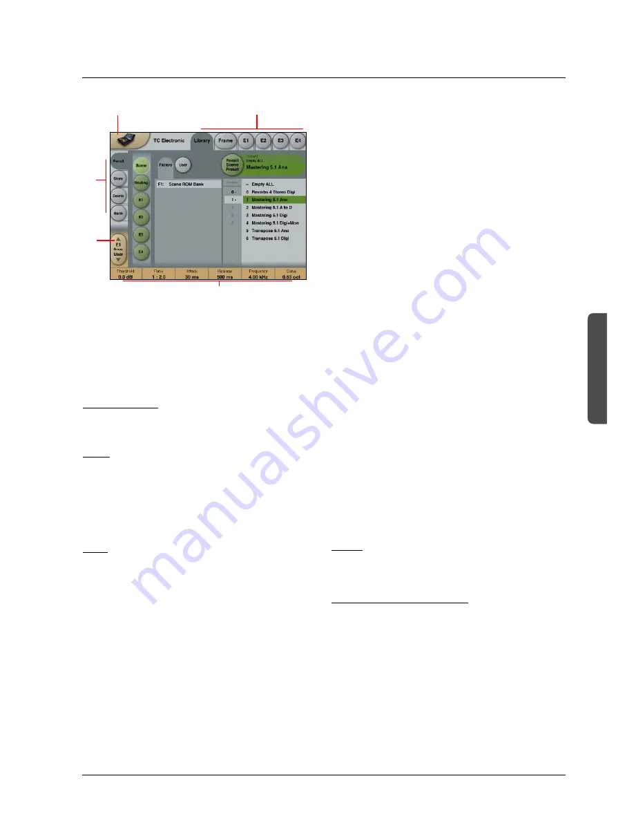
The Library-Recall page illustrated in Fig.3 leads to
explanation of the “operating levels” in the System 6000.
We differentiate between 3 levels of presets: Scene,
Routing and Engine levels.
• SCENE
This is the most extensive selection you can make. It
includes all four Engine algorithms as well as Physical
and virtual Engine connections. A Scene recall can be
compared to a “total recall.”
• ROUTING
Handles all I/O Routings, including all physical
I/O connections to the Engine I/O’s. No algorithm
(Engine) settings are recalled/stored with this selection.
A Routing preset holds all parameters displayed on the
Frame-Routing page.
• ENGINE
Handles the current algorithm in the selected Engine.
A single preset can be loaded to each of the four
Engines.
Parameter Values and Fader Groups
In the bottom of the display, Fader assignments and values
will always reflect the last modified Engine. Most
parameters can be controlled via the 6 Faders. As some
algorithms hold numerous parameters and we operate with
6 Faders the preset parameters are organized in Fader
Groups. To scroll between the Fader Groups use the
Fader Group
selectors.
Parameter value - Fine Adjust
Any parameter value can be adjusted in two accuracies.
A Normal and a Fine Adjust - mode. To switch between the
two modes press the Value Fields above the faders.
As shown in the illustration the Fine Adjust mode will be
indicated with two triangles in the value field.
Fader 6
Any parameter can always be assigned to Fader 6 by
pressing the parameter. Detailed explanation will follow in
the next sections.
User Fader Group - Custom Group
A User Fader group where you can assign parameters to
all 6 faders can also be created and saved along with the
preset. The User Fader group is selected by pressing the
Fader Group
selectors.
Fader
Group
Selector
Function
Select
Tabs
Library, Frame &
Engine select Tabs
Parameter values present
in the currently recalled
preset.
Basic TC Icon operation
Navigation in the TC Icon display is easily done when a few
basic elements are explained.
The Icon
Link
key in the upper left corner allows you to
navigate between the two pages/modes illustrated on the
previous page.
In both modes you:
• Press the top-tabs to do primary selections
• Press the side-tabs or elements to do secondary
selections.
Fig. 1:
Via the “overall”
Select & Setup
pages you access
overall settings and choices like:
• Selection of which mainframe to operate
• Setting up IP addresses for connected units
• Enable devices to network
• Updates via network or disk
• TC Icon settings such as display appearance
Fig. 2:
The selection of mainframe is done in the Select page
illustrated in “Fig 1”. The page/pages illustrated in Fig. 2
are pages containing parameters on a specific mainframe.
These are the Operating Pages and the page you will be
working in once the system is up and running. Only when
several mainframes are connected you will need to go to
the “overall” Select and Setup pages to switch
mainframe.
The Icon
LINK key


