background image


RAYTHON User Manual V1.0 

protected by installed PV 
switch   


Negative   

PE 

Ground Connection


PE 


4.7 Wiring Instruction 

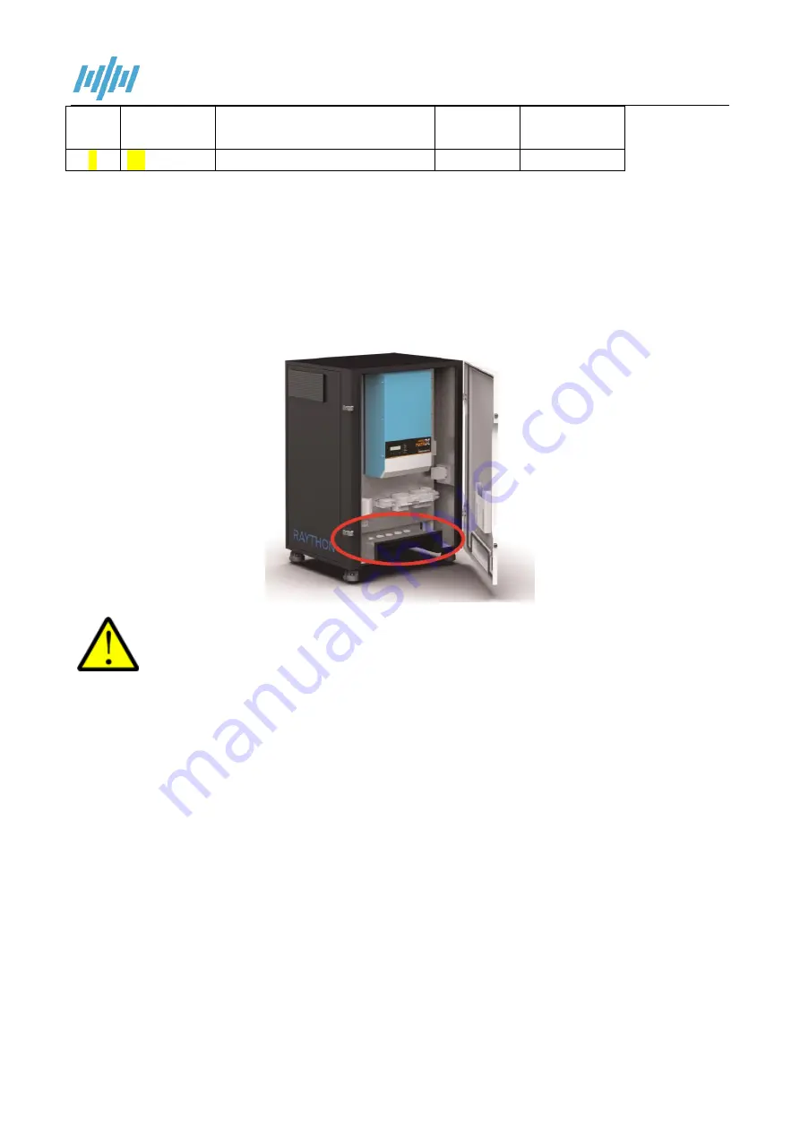
All of the cables should be inserted into the cabinet through the holes at the bottom of the cabinet as 
below picture shows. 


Cut off the power before installation for safety. Please make sure the inverter is switched 
off and DC MCB is turn off at front panel before installation. 


4.7.1 Connecting to Earth 

At the bottom of the enclosure, there is a ground terminal. See wiring area view. Please connect it with EARTH or 

vehicle chassis by a 6~10mm²

 green yellow wire (keep wire size same with AC input cable). 

Summary of Contents for Raython Series

Page 1: ...Raython series All in one Standalone Solar Power System Off Grid For Outdoor Use USER MANUAL Version 1 0 Date DEC 2021 ...

Page 2: ...e your reliable power solution provider D Di is sc cl la ai im me er r Unless specially agreed in writing TBB Power Co Ltd Take no warranty as to the accuracy sufficiency of suitability of any technical or other information provided in this manual or other documentation Assumes no responsibility or liability for loss or damage whether direct indirect consequential or incidental which might arise o...

Page 3: ...e DC input voltage or battery voltage is the same to the nominal input voltage of this inverter 2 Please connect positive terminal of the battery to input of the inverter 3 Please connect negative terminal of the battery to input of the inverter 4 Please use the shortest cable to connect and ensure the secure connection 5 While connecting please secure the connection and avoid short cut between po...

Page 4: ...4 1 Material List 13 4 2 Location 13 4 3 Placement 14 4 4 Fix the castor 15 4 4 Fix the Cabinet 15 4 5 Wiring Recommendation 16 4 6 Connection Terminal Description 16 4 7 Wiring Instruction 17 4 7 1 Connecting to Earth 17 4 7 2 Connecting AC Grid Cable 18 4 7 3 Connecting the Loads 19 4 7 4 Connecting PV in Cable 20 4 7 5 Connecting the AGS Terminal 20 4 8 All Switches of the unit 21 5 0 Operation...

Page 5: ...1 2 Symbols Used in the Documentation This symbol indicates a hazardous situation which if not avoided could result in death or serious injury This symbol indicates a situation which if the instructions are not followed could result in injury and damage to the equipment This symbol indicates a situation which if the instructions are not followed could result in damage to the equipment 1 3 General ...

Page 6: ...l operating conditions such as a charger malfunction It is the responsibility of the customer to provide adequate ventilation so that hydrogen gas accumulation in battery area does not exceed 2 by volume However normal air circulation in a ventilated facility will preclude any hydrogen build up even during cyclic charging Never install batteries in a sealed cabinet or enclosure REMOVE all personal...

Page 7: ...ll in one design for easy and quicker installation 3 hours Provided with IP54 protection index for outdoor use Factory assembled and tested system enable you get free from complicated groundwork ECO friendly lower pollution less noise and lower fuel consumption AGS Function automatically start and stop the generator according to the load level battery level or time period to ensure continuous powe...

Page 8: ...RAYTHON User Manual V1 0 2 1 Raython Cabinet Dimensions ...

Page 9: ...y leading efficiency for mission critical application Its distinguishing surge capability makes it capable to power most demanding appliances such as air conditioner water pump washing machine freezer etc With the function of power assist power control it can be used to work with a limited AC source such as generator or limited grid Apollo Matrix can automatically adjust its charging current to av...

Page 10: ...able to power most demanding appliances such as air conditioner water pump washing machine freezer etc With the function of power assist power control it can be used to work with a limited AC source such as generator or limited grid Kinergier Pro can automatically adjust its charging current to avoid grid or generator to be overloaded In case of temporary peak power appears it can work as a supple...

Page 11: ...d Carbon battery and lithium ion battery were available upon request For more information about Solar Mate please refer to its manual 2 5 Kinergy Data Logging Stick Available with GPRS and WIFI version wireless data logger is an external communication device connected to the TBB inverter through DB9 interface Through NOVA web or APP it offers a convenient way to monitor the system performance remo...

Page 12: ...RAYTHON User Manual V1 0 For more information about Kinergy please refer to its manual ...

Page 13: ...ter MPPT charge Controller Kinergy and Li ion battery modules As following diagram shows through monitoring the real time output power energy consumption of the connected appliances and the battery SOC Raython will automatically change the work mode to keep your loads being powered ...

Page 14: ...uter carton Raython Raython User manual Kinergy User manual Apollo Matrix User manual Kinergier Pro User manual Solar Mate User manual 4 2 Location Please install the equipment in a location of Dry Clean Cool with good ventilation Working temperature 20 60 Storage temperature 40 70 Relative Humidity 0 95 non condensing Cooling Forced air Keep it away from fire high temperature inflammable explosiv...

Page 15: ...urface Do not place the unit in an inclined position Do not store the unit on its side or up side down to avoid the damage of the unit Following minimum clearance are requested for the installation Direction Minimum Clearance Front 1m Back 0 3m Left Side 0 3m Right Side 1m Top 0 3m ...

Page 16: ... Clockwise rotating the nut A shown on the below picture with a spanner or other proper tool 4 4 Fix the Cabinet Fix the foot support to the bottom of the cabinet and take a point at the screw hole of each foot support Then drill a suitable hole and put the expansion screws into the hole Finally push the cabinet into the hole position and fix the expansion screws ...

Page 17: ...V input 16mm 55A AGS cable 1 mm 4 6 Connection Terminal Description Item Name Description Label Comments 1 Relay1 Connect to generator start control port NO C 2 Relay2 Connect to generator start control port NO C 3 AC in Connect to the grid AC input L Line N Neural 4 AC Out1 General load without being protected by installed MCB L Line N Neural 5 AC Out2 General load without being protected by inst...

Page 18: ...e cabinet as below picture shows Cut off the power before installation for safety Please make sure the inverter is switched off and DC MCB is turn off at front panel before installation 4 7 1 Connecting to Earth At the bottom of the enclosure there is a ground terminal See wiring area view Please connect it with EARTH or vehicle chassis by a 6 10mm green yellow wire keep wire size same with AC inp...

Page 19: ...g AC Grid Cable For safety please turn off the Main Input MCB before the installation Using correct cable gauge refer to chapter 4 4 please connect the grid to the terminal labeled AC IN Make sure the connection is correct and tightly screwed ...

Page 20: ... generator Two groups of output terminals are supplied with this RAYTHON system The labeled terminal is supplied with protected MCB Using correct cable gauge refer to chapter 4 4 please connect the load to the terminal labeled AC OUT1 AC OUT2 Make sure the connection is correct and tightly screwed 有些机型 AC OUT 接在 MCB 上 For some models the AC OUT is connected to the MCB ...

Page 21: ...PV Input MCB before the installation Using correct cable gauge refer to chapter 4 4 please connect the PV to the terminal labeled PV IN Ensure that the positive and negative poles are not reversed Make sure the connection is correct and tightly screwed 4 7 5 Connecting the AGS Terminal ...

Page 22: ...als are supplied with this RAYTHON system Using correct cable gauge refer to chapter 4 4 please connect the load to the terminal labeled Relay1 Relay2 Make sure the connection is correct and tightly screwed 4 8 All Switches of the unit Battery Switch ...

Page 23: ...RAYTHON User Manual V1 0 PV isolate Switch AC MCB ...

Page 24: ...RAYTHON User Manual V1 0 ...

Page 25: ...al range 5 2 Switching on the Battery Make sure the battery voltage is within the permissible range before turning ON the breaker Switch on all batteries Press the On Off button for 0 5 second to turn on the batteries Switch on battery switch 5 3 Switch on the Inverter Please follow the below instructions step by step Step 1 Press the On Off button for 2 seconds to turn on the inverter into the st...

Page 26: ...AYTHON User Manual V1 0 Apollo Matrix interface Kinergier Pro interface 5 4 Power on PV Close the PV IN Switch to power The MPPT Charge Controller will start to charge the battery Apollo Matrix interface ...

Page 27: ...ep 3 Turn off the circuit breaker of PV input and AC input Step 4 Turn off the circuit breaker between the battery and the inverter 5 6 Bypass Switch Application When the system fails to supply power you can use this switch to supply power to the load from the grid or generator The power is only supplied to the load connected to the AC OUT1 Step 1 turn off the AC OUT1 and AC input break Step2 turn...

Page 28: ...RAYTHON User Manual V1 0 5 7 Connect to the NOVA Monitoring Platform Please refer to the User Manual of Kinergy and Quick Installation Guide more details please visit www tbbpower com ...

Page 29: ...ge 175 265VAC AC Wave Harmonic Adaption Weak AC Source Battery Type TBB Super L SOC Low Protect 10 SOC Low Warning 20 SOC charge Enough 80 AC in Logic AC in First mode AC OUT2 Control Power By AC in Relay Control AGS Function GEN Start SOC 30 GEN Stop SOC 80 GEN load control Disable GEN Time Window Disable Relay 1 signal type Level Relay 2 signal type Pulse For more settings please refer to its ma...

Page 30: ...nput Current transfer switch A 50 Inverter Product Topology Transformer based Nominal battery voltage VDC 48 Input voltage range VDC 42 68 AC output voltage VAC 220 230 240 2 AC output frequency Hz 50 60 0 1 Harmonic distortion 2 Load power factor 1 0 Cont output power at 25 C VA 5000 6500 Max output power at 25 C W 5000 8000 Peak power 10 sec W 8000 13000 Surge 300 Maximum efficiency 96 ...

Page 31: ...ltage V 150 Maximum PV short circuit Current A 60 80 MPPT voltage range V 65 145 MPPT charger maximum efficiency 98 MPPT efficiency 99 5 99 9 Battery Battery Type LiFePO4 Li ion battery Nominal Energy Capacity 5 1kWh 20 4kWh General data General purpose com Port GPRS WIFI optional with Kinergy Operating temperature range Inverter 20 C to 65 C Battery discharge 20 C to 55 C charge 0 40 Relative hum...

Page 32: ...m max 600 700 1100 Net Weight kg 120kg without battery 130kg without battery Cooling Forced fan Protection index IP54 Standards Safety EN IEC 62477 1 EN IEC 62109 1 EN IEC 62109 2 EN IEC 60950 1 EN IEC 62109 2 EMC EN61000 6 1 EN61000 6 2 EN61000 6 3 EN61000 3 11 EN61000 3 12 ...

Page 33: ...TBB Power Co Ltd Web www tbbpower com Tel 86 592 5796068 5796287 Fax 86 592 5796070 Email TBBSupport tbbpower com ...

Reviews: