background image

Section 8

8-1 

Model C612

Troubleshooting Guide 

 8

Troubleshooting Guide

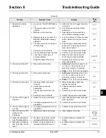
Table 8-1

Problem

Probable Cause

Remedy

Page 

 Ref.

1. No product is being 

dispensed. 

a. Low on mix. The MIX OUT light is 

on.

a. Add mix to the mix hopper. Return to 

Auto mode.

6-13

b. The power switch is in the OFF 

position.

b. Turn the power switch to ON and 

select Auto.

6-13

c. Machine not in Auto mode.

c. Select Auto and allow machine to 

cycle off before drawing product.

6-13

d. Beater motor is out on reset. The 

BEATER OVERLOAD message 
displayed.

d. Turn the machine off. Press the reset 

button. Restart the machine in Auto 
mode.

5-3

e. The pump motor is not running in 

the Auto mode.

e. Push the pump reset button. Check 

pump motor is operating when the 
draw valve is raised.

5-3

f. Freeze-up in mix inlet hole.

f. Contact a Taylor service technician.

- - -

g. The mix pump ball crank is broken.

g. Contact a Taylor service technician.

- - -

h. Feed tube or check ring not 

properly installed.

h. Make sure feed tube and rubber 

check ring are properly installed.

6-9,6-10

i. Butterfat buildup in the pump.

i. Carefully remove the mix pump. 

Clean and re-install.

6-7

2. The product is too stiff.

a. Draw rate is set too slow.

a.

Soft Serve: 

Adjust draw rate of 5 oz. 

to 7-1/2 oz. (148 ml to 222 ml) of 
product by weight in 10 seconds.

a.

Shake: 

7 fl. oz. (207 ml) in 5 seconds.

5-3

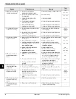
3. The product is too soft.

a. Draw rate is set too fast.

a.

Soft Serve:

 Adjust draw rate of 5 oz. 

to 7-1/2 oz. (148 ml to 222 ml) of 
product by weight in 10 seconds.

a. Shake: 

7 fl. oz. (207 ml) in 5 seconds.

5-3

4. The product is too thick.

a. Freezing cylinder not primed 

correctly.

a. Drain the freezing cylinder and 

reprime the machine.

6-13

b. Air/mix pump incorrectly 

assembled.

b. Follow assembly procedures 

carefully.

6-7

c. The viscosity control is set too 

cold.

c. Contact a Taylor service technician.

- - -

d. Freeze-up in mix inlet hole.

d. Contact a Taylor service technician.

- - -

5. The mix in the hopper is 

too warm.

a. Hopper cover is not in position.

a. Clean and sanitize hopper cover and 

place in position.

6-13

b. The hopper temperature is out of 

adjustment.

b. Contact a Taylor service technician.

- - -

6. The mix in the hopper is 

too cold.

a. The hopper temperature is out of 

adjustment.

a. Contact a Taylor service technician.

- - -

7. MIX LOW and MIX OUT 

probes are not 
functioning.

a. Milkstone buildup in the hopper.

a. Clean hoppers thoroughly.

6-14 

through

 6-16

8. Product is collecting on 

top of the freezer door.

a. The top O-ring on draw valve is 

improperly lubricated or worn.

a. Lubricate properly or replace the 

O-ring.

6-2, 6-5

9. Excessive mix leakage 

from the bottom of door 
spout.

a. Bottom O-ring on draw valve is 

improperly lubricated or worn.

a. Lubricate properly or replace the 

O-ring.

6-2, 6-5

Summary of Contents for C612

Page 1: ...OPERATOR S MANUAL Model C612 Combination Freezer 9 27 19 Original Publication Updated 9 3 2020 Original Operating Instructions 088698 M...

Page 2: ...__ Cycle__________ Phase__________________________________ Maximum Fuse Size ______________________________________________________ A Minimum Wire Ampacity ____________________________________________...

Page 3: ...el C612 Beater Door Assembly Soft Serve Side 4 4 X57028 14 Pump A Mix Simplified Shake 4 5 X57029 12 Pump A Mix Simplified Soft Serve 4 6 088671 Parts Tray Shake Side 4 7 088672 Parts Tray Soft Serve...

Page 4: ...ing Cleaning and Sanitizing 7 1 Troubleshooting Bacterial Count 7 1 Regular Maintenance Checks 7 1 Winter Storage 7 2 Section 8 Troubleshooting Guide Section 9 Parts Replacement Schedule Section 10 Li...

Page 5: ...This machine has many sharp edges that can cause severe injuries Site Preparation Review the area where the machine will be installed before uncrating the machine Make sure that all possible hazards...

Page 6: ...uires one power supply for each data label on the machine Check the data label s on the machine for branch circuit overcurrent protection or fuse circuit ampacity and other electrical specifications S...

Page 7: ...AUTION This machine contains fluorinated greenhouse gases F Gas to provide refrigeration using a hermetically sealed circuit or within foam insulation This machine s type of gas quantity Global Warmin...

Page 8: ...1 4 TO THE INSTALLER Model C612 To the Installer 1 Notes...

Page 9: ...f the parts are authorized Taylor parts purchased from the local authorized Taylor distributor and only if all required service work is provided by a Taylor service technician Taylor reserves the righ...

Page 10: ...act known to any technician he or she employs It should also be noted that Taylor does not warrant the refrigerant used in its equipment For example if the refrigerant is lost during the course of ord...

Page 11: ...marked by the equipotential bonding symbol 5021 of IEC 60417 1 on both the removable panel and the machine s frame WARNING Avoid injury DO NOT operate the machine unless it is properly grounded DO NO...

Page 12: ...n where its use and maintenance is restricted to trained personnel Failure to comply may result in personal injury CAUTION This machine must be placed on a level surface Extreme care should be taken w...

Page 13: ...Section 4 4 1 Model C612 Operator Parts Identification 4 Operator Parts Identification Figure 4 1 6 22 3 4 25 27 28 26 5 6 8 7 10 11 12 13 14 17 16 21 9 20 19 18 24 15 23 1 2 29...

Page 14: ...11 11 Panel A Filter Louvered X59928 12 Caster 4 SWV 3 4 10 STM 044106 13 Screw 1 4 20 X 3 8 RHM 011694 14 Panel Corner Frnt R 063087 15 Deflector Blower Exh 084447 Item Description Part No 16 Caster...

Page 15: ...6332 3 Nut 5 16 24 Finished Hex 029639 BLK 4 O ring 1 4 OD x 070W 50 Duro 25 to Bag 015872 SER 5 Handle A Draw X83800 1 6 O ring 7 8 OD x 03W 100 to Bag 014402 SER 7 Valve A Draw C612 X88542 Item Desc...

Page 16: ...9639 BLK 4 O ring 1 4 OD x 070W 50 Duro 25 to Bag 015872 SER 5 Handle A Draw X83800 1 6 O ring 7 8 OD x 103W 100 to Bag 014402 SER 7 Valve A Draw C706 X56072 8 Plug Prime 028805 9 O ring 3 8 OD x 070W...

Page 17: ...y Mix Simplified Shake X57028 14 1 Cylinder Pump Hopper Shake 057944 2 Pin Retaining X55450 3 Piston Pump Simplified 053526 4 O ring 2 1 8 OD X 139W 225 50 to Bag 020051 SER 5 Cap Valve Body Shake 056...

Page 18: ...tion Part No 1 7 Pump Assembly Mix Simplified Soft Serve X57029 12 1 Cylinder Pump Hopper Soft Serve 057943 2 Pin Retaining X55450 3 Piston 053526 4 O ring 2 1 8 OD x 139W 225 50 to Bag 020051 SER 5 C...

Page 19: ...Item Description Part No 1 Beater A 7 qt X50958 2 Blade Scraper 16 041103 3 Pin Handle 055819 4 Handle A Draw X83800 1 5 Shaft Beater 050985 6 Valve A Draw X56072 Item Description Part No 7 Bearing Do...

Page 20: ...55819 3 O ring 3 8 OD x 070W 016137 4 Nut Stud Short 055989 5 O ring 7 8 OD x 103W 014402 6 Plug Prime 028805 7 Gasket Door HT 4 Double 048926 8 Door A w Baffle C612 SS X88602 Item Description Part No...

Page 21: ...100 packs or Kay 5 part no 041082 125 packs Not Shown 5 4 2 6 1 8 3 7 9 Item Description Part No 1 Pail 10 qt 013163 2 Tool O ring Removal 048260 WHT 3 Bottle Wash Plastic 044818 4 Tool Mix Pump Shaft...

Page 22: ...s Figure 4 9 z 1 2 3 4 5 6 7 Item Description Part No 1 Black Bristle Brush 1 X 2 013071 2 Double End Brush 013072 3 Blue Bristle Brush 1 x 2 013073 4 Brush Set 3 050103 Item Description Part No 5 Bru...

Page 23: ...8 6 7 9 10 11 12 6 7 8 1 5 4 5 4 Item Description 1 Power Switch 2 Fluorescent Display 3 Auto Key 4 Wash Key 5 Mix Pump Key 6 MIX OUT Indicator Item Description 7 Standby Key 8 MIX LOW Indicator 9 Sel...

Page 24: ...Indicator Lights MIX LOW When the MIX LOW symbol is illuminated the mix hopper has a low supply of mix and should be refilled as soon as possible MIX OUT When the MIX OUT symbol is illuminated the mix...

Page 25: ...mechanism will trip To reset the pump press the reset button firmly CAUTION DO NOT use metal objects to press the reset button Failure to follow this instruction may result in electrocution Adjustable...

Page 26: ...SEL symbol or the Manager s Menu is selected The display screen will also alert the operator of specific faults detected by the control Power Up When the machine is powered the control system will ini...

Page 27: ...e SEL symbol to set the first code number in the cursor position When the correct number is selected press the SEL symbol to move the cursor to the next number position Continue to enter the proper ac...

Page 28: ...hanges have been made and the year has been set pressing the SEL key will display the first DAYLIGHT SAVING TIME DST screen Pressing the Up or Down arrow keys will move the arrow to Enable or Disable...

Page 29: ...the next screen Program the AUTO START TIME by pressing the Up arrow key to move the arrow to Change Press the SEL key to advance to the next screen Use the arrow keys to program the AUTO START TIME...

Page 30: ...escent display is on the front control panel During normal operation the display is blank The display is used to show menu options and notifies the operator if a fault is detected On international mod...

Page 31: ...L R COMP ON TOO LONG The compressor run time exceeded the 11 minute timer L R PRODUCT TOO COLD In Auto mode the mix temperature in the left or right barrel was too low This may indicate a starved barr...

Page 32: ...e Pin The NET SERVICE PIN allows the manager or service technician to initialize a network connection for networking kitchens Pressing the Up or Down arrow key will move the arrow to Yes or No Pressin...

Page 33: ...e beater driveshaft before installing Slide the beater driveshaft boot seal over the small end of the beater driveshaft and engage it into the groove on the shaft Heavily lubricate the inside portion...

Page 34: ...seated the beater will not protrude beyond the front of the freezing cylinder 6 Before assembling the freezer door check the following for any nicks cracks or signs of wear the door bearing door gask...

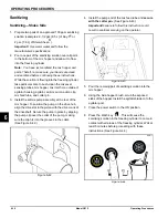
Page 35: ...he OFF position Failure to follow this instruction may result in severe personal injury from hazardous moving parts Set up using the parts tray for the soft serve side 1 Lubricate the groove on the so...

Page 36: ...a scraper blade is nicked or worn replace both blades Figure 6 15 4 If the blades are in good condition place the rear scraper blade over the rear holding pin on the beater Figure 6 16 Note Soft serve...

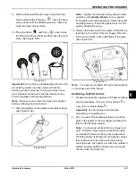
Page 37: ...See Figure 6 19 Figure 6 19 9 Before assembling the freezer door check the following for any nicks cracks or signs of wear the door bearing door gasket draw valve O rings and all sides of the door ass...

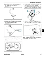
Page 38: ...secured See Figure 6 24 Figure 6 24 15 Install the draw handle Slide the fork of the draw handle in the slot of the draw valve Secure it with the pivot pin See Figure 6 25 Figure 6 25 Note This machin...

Page 39: ...d condition for the pump and entire machine to operate properly They cannot properly serve their intended function if nicks cuts or holes in the material are present Inspect the plastic pump parts for...

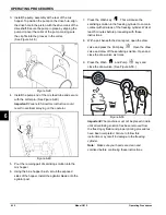
Page 40: ...nsert the valve cap into the hole in the mix inlet adapter See Figure 6 34 Figure 6 34 8 Insert the mix inlet assembly into the pump cylinder See Figure 6 35 Figure 6 35 Note The adapter must be posit...

Page 41: ...er pin and agitator in the bottom of the mix hopper for sanitizing See Figure 6 39 Figure 6 39 13 Slide the large black O ring and the two smaller black O rings into the grooves on the driveshaft Thor...

Page 42: ...3 Install the air mix pump assembly at the rear of the mix hopper To position the pump on the drive hub align the drive slot in the piston with the drive crank of the driveshaft Secure the pump in pl...

Page 43: ...sh clean with sanitizing solution Install the agitator back onto the agitator driveshaft housing 12 Remove the cotter pin from the pump Stand the mix feed tube in the corner of the mix hopper Place th...

Page 44: ...exposed sides of the hopper Install the agitatior blade onto the agitator post 7 Press the Wash key This will cause the sanitizing solution in the freezing cylinder to come in contact with all areas o...

Page 45: ...ve immediately to remove all sanitizing solution When only fresh mix is flowing close the draw valve 3 Once a steady stream of mix starts to flow from the prime plug opening in the bottom of the freez...

Page 46: ...ash mode 2 With a pail beneath the door spouts raise the prime plug soft serve side only and press the Wash symbol See Figure 6 54 Figure 6 54 3 When a steady stream of rinse water is flowing from the...

Page 47: ...ruction may result in severe personal injury from hazardous moving parts 1 Remove the handscrews freezer door beater and scraper blades and driveshaft with the driveshaft seal from the freezing cylind...

Page 48: ...h the freezer are available for brush cleaning 2 Thoroughly brush clean all disassembled parts in the cleaning solution making sure all lubricant and mix film is removed Make sure to brush all surface...

Page 49: ...zing The temperature of mix in the mix hopper and walk in cooler should be below 40 F 4 4 C Discard the remaining mix from the freezer during the cleaning procedures Regular Maintenance Checks Replace...

Page 50: ...any water remaining in the condenser Important Failure to follow this procedure may cause severe damage to the refrigeration system Your local Taylor distributor can perform this winter storage servi...

Page 51: ...uct by weight in 10 seconds a Shake 7 fl oz 207 ml in 5 seconds 5 3 3 The product is too soft a Draw rate is set too fast a Soft Serve Adjust draw rate of 5 oz to 7 1 2 oz 148 ml to 222 ml of product...

Page 52: ...uto only after priming is complete and all sanitizing solution is removed 6 10 6 13 d Broken freezer door baffle rod d Replace freezer door 6 6 e Broken beater pins e Replace beater assembly 6 2 6 4 f...

Page 53: ...p Valve Gasket X Mix Feed Tube Check Ring X Pump Driveshaft O ring X Blue Bristle Brush 3 x 7 Inspect and replace if necessary Minimum White Bristle Brush 3 x 1 2 Inspect and replace if necessary Mini...

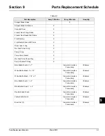
Page 54: ...9 2 PARTS REPLACEMENT SCHEDULE Model C612 Parts Replacement Schedule 9 Notes...

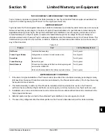
Page 55: ...WARRANTY CONDITIONS 1 If the date of original installation of the Product cannot be verified then the limited warranty period begins ninety 90 days from the date of Product manufacture as indicated by...

Page 56: ...due to theft vandalism wind rain flood high water water lightning earthquake or any other natural disaster fire corrosive environments insect or rodent infestation or other casualty accident or condi...

Page 57: ...OR INCIDENTAL DAMAGES INCLUDING CLAIMS FOR LOST SALES LOST PROFITS PRODUCT LOSS PROPERTY DAMAGES OR SERVICE EXPENSES ARE EXPRESSLY EXCLUDED THE EXPRESS WARRANTIES MADE IN THIS LIMITED WARRANTY MAY NOT...

Page 58: ...10 4 LIMITED WARRANTY ON EQUIPMENT Model C612 Limited Warranty on Equipment 10 Notes...

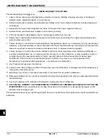
Page 59: ...ed proof of purchase may be required at time of service 2 This limited warranty is valid only if the Part is installed and all required service work in connection with the Part is performed by an auth...

Page 60: ...arranty service work promptly upon arrival 9 Failure damage or repairs due to faulty installation misapplication abuse no or improper servicing unauthorized alteration or improper operation or use as...

Page 61: ...NCIDENTAL DAMAGES INCLUDING CLAIMS FOR LOST SALES LOST PROFITS PRODUCT LOSS PROPERTY DAMAGES OR SERVICE EXPENSES ARE EXPRESSLY EXCLUDED THE EXPRESS WARRANTIES MADE IN THIS LIMITED WARRANTY MAY NOT BE...

Page 62: ...11 4 LIMITED WARRANTY ON PARTS Model C612 Limited Warranty on Parts 11 Notes...

Reviews: