6-10
OPERATING PROCEDURES
Model C612
Operating Procedures
6
Sanitizing
Sanitizing—Shake Side
1. Prepare two pails of an approved 100 ppm sanitizing
solution (examples: 2-1/2 gal. [9.5 L] of Kay-5
®
or
2 gal. [7.6 L] of Stera-Sheen
®
).
Important!
Use warm water and follow the
manufacturer's specifications.
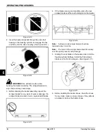
2. Pour one pail of the sanitizing solution over all parts
in the bottom of the mix hopper and allow it to flow
into the freezing cylinder.
Note:
You have just sanitized the mix hopper and
parts. Therefore, make sure your hands are clean
and sanitized before continuing these instructions.
While the solution is flowing into the freezing cylinder,
take particular care to bush-clean the mix-level
sensing probes, mix hopper, mix inlet hole, outside of
agitator housing, agitator, air/mix pump, pump clip,
mix feed tube, and cotter pin.
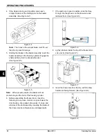
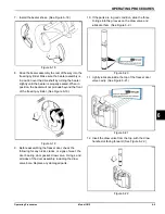
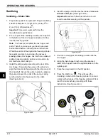
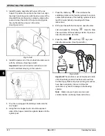
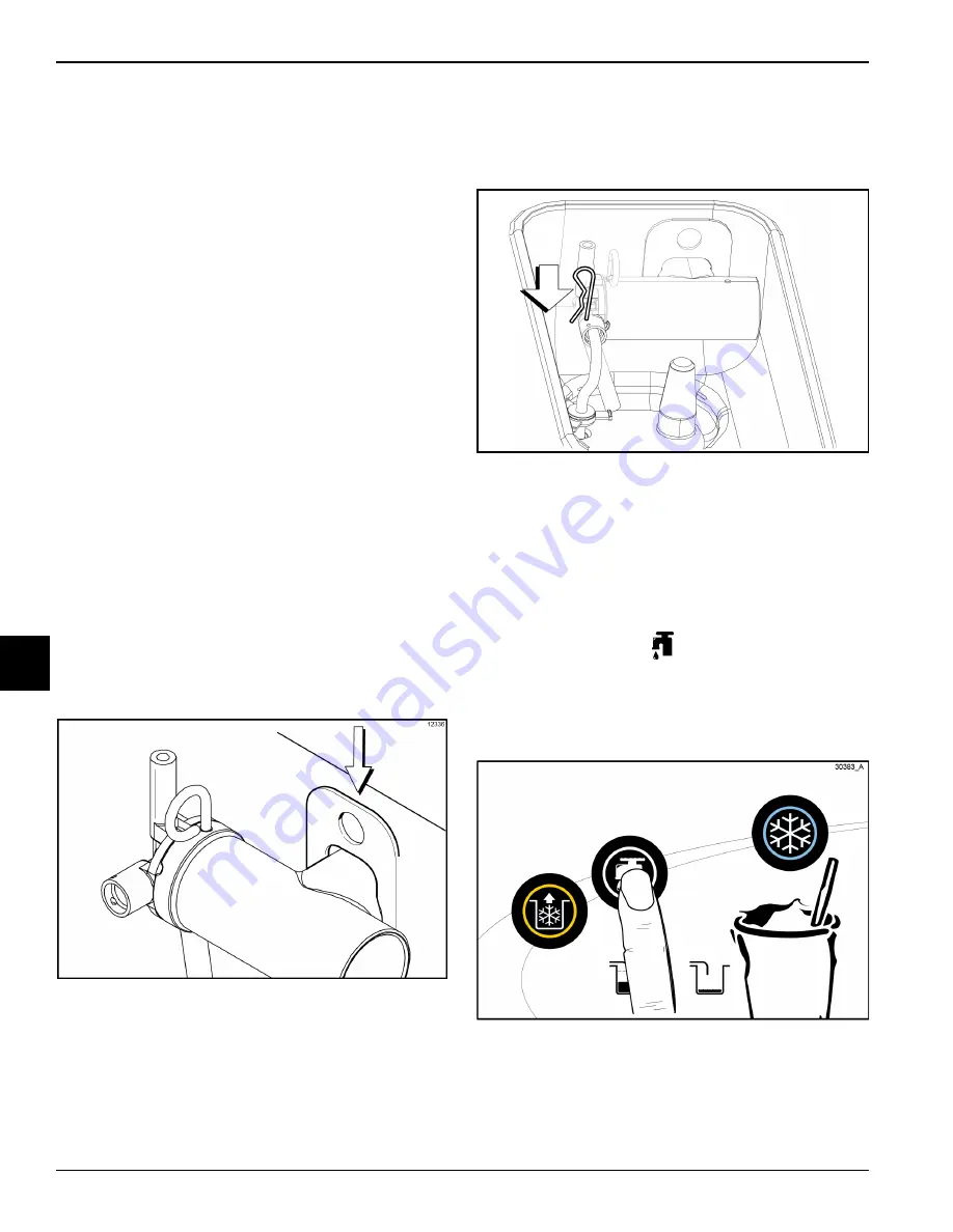
3. Install the air/mix pump assembly at the rear of the
mix hopper. To position the pump on the drive hub,
align the drive slot in the piston with the drive crank of
the driveshaft. Secure the pump in place by slipping
the pump clip over the collar of the pump, making
sure the clip fits into the grooves in the collar.
(See Figure 6-42.)
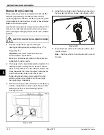
Figure 6-42
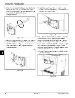
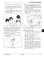
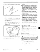
4. Install the pump end of the mix feed tube and
secure
with the cotter pin
. (See Figure 6-43.)
Important!
Failure to follow this instruction could
result in sanitizer spraying on the operator.
Figure 6-43
5. Pour the remaing pail of sanitizing solution into the
mix hopper.
6. Using the blue hopper brush, scrub the exposed
sides of the hopper. Install the agitator blade onto the
agitator post.
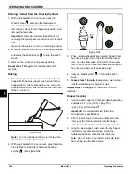
7. Place the power switch in the ON position.
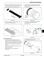
8. Press the Wash key
. This will cause the
sanitizing solution in the freezing cylinder to come in
contact with all areas of the freezing cylinder. Wait at
least 5 minutes before proceeding with these
instructions. (See Figure 6-44.)
Figure 6-44
Summary of Contents for C612
Page 8: ...1 4 TO THE INSTALLER Model C612 To the Installer 1 Notes...
Page 54: ...9 2 PARTS REPLACEMENT SCHEDULE Model C612 Parts Replacement Schedule 9 Notes...
Page 58: ...10 4 LIMITED WARRANTY ON EQUIPMENT Model C612 Limited Warranty on Equipment 10 Notes...
Page 62: ...11 4 LIMITED WARRANTY ON PARTS Model C612 Limited Warranty on Parts 11 Notes...

