

Models 369/370/371
5
ENGLISH
4 TO OPERATE SAFELY
1 -
Do not
operate the dispenser without reading this
operator’s manual.
2 -
Do not
operate the dispenser unless it is properly
grounded.
3 -
Do not
use extension cords to connect the dispenser.
4 -
Do not
operate the dispenser unless all panels are
restrained with screws.
5 -
Do not
obstruct air intake and discharge openings: 15 cm
(6”) minimum air space around all sides of the dispenser.
6 -
Do not
put objects or fingers in panels louvers and faucet
outlet.
7 -
Do not
remove bowls, augers and panels for cleaning or
routine maintenance unless the dispenser is disconnected
from its power source.
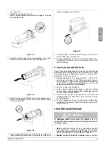
5 OPERATING PROCEDURES
1 - Clean and sanitize the unit according to the instructions in
t h i s m a n u a l . S e e c h a p t e r 5 . 3 C L E A N I N G A N D
SANITIZING PROCEDURES.
2 - Fill the bowls with product to the maximum level mark. Do
not overfill.
The exact quantity of product (expressed as liters and
gallons) is shown by marks on the bowl.
3 - In case of products to be diluted with water, pour water into
bowl first, then add correct quantity of product. It is
advisable to strain the natural fruits to prevent pulps from
obstructing the faucet outlet.
4 - To obtain the best performance and result, use bases
designed to be run in Granita freezers.
If natural juices (e.g. lemon, orange) as well as sugarless
products (e.g. coffee) are used, dissolve 150 - 200 grams
of sugar per liter.
5 - For soft drink use the unit doesn’t need any minimun brix
level.
6 - Install the covers and check that they are correctly placed
over the bowls. The dispenser must always run with the
covers installed to prevent possible contamination of the
product.
7
- Set the control switches as shown in chapter
5.1 DESCRIPTION OF CONTROLS.
8 - Always leave the dispenser on, as the refrigeration stops
automatically when Granita reaches the proper thickness.
The mixers will continue to turn.
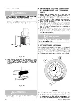
5. 1 DESCRIPTION OF CONTROLS
The dispenser is equipped with a power switch and a light
switch. In addition each bowl is individually operated by a
mixer/refrigeration switch. In fact it is possible to dispense both
soft drinks and Granita.
When a bowl is in Soft Drink mode, the beverage temperature
is controlled by the corresponding thermostat.
When a bowl is in Granita mode, the mix viscosity is controlled
by the corresponding adjustment screw located in the rear wall
of each container (for temperature and viscosity setting refer to
chapter 5.2 OPERATION HELPFUL HINTS).
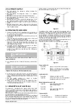
All the switches are located on the faucet side of the dispenser
behind switch covers (see figure 2).
figure 2
In addition all the models except 369 are equipped with an
automatic safety pressure switch to prevent damages to the
compressor. The lighting of the light at the left of the switch
covers indicates insufficient ventilation of the unit. If this occurs
check that there is sufficient space on all sides for ventilation
(at least 15 cm (6”) on each side) and that condenser filter is
free from dust or other obstructions.
In case the warning light is still ON after these operations have
been carried out a service call is required.
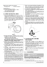
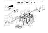
Dispenser controls functions are as follows (see figure 3):
figure 3
Power switch (A)
Light switch (E)
Mixer/refrigeration switch (B)
Thermostat (D)
IMPORTANT
Brix (sugar percent content) must be at least 13 for all
granita products.
IMPORTANT
Operate the dispenser with food products only.
0 position
:
power is turned OFF to all functions.
I position
:
power is turned ON to all functions
and the other switches are enabled.
The fan motor runs.
0 position
:
all top cover lights are OFF.
I position
:
all top cover lights are ON, provided
that power switch (A) is set to I.
I position
:
mixer and refrigeration ON.
SOFT DRINK mode.
0 position
:
OFF.
II position
:
mixer and refrigeration ON.
GRANITA mode.
Turn clockwise
: to decrease temperature
Turn counterclockwise
: to increase temperature