Taylor 345, Operator'S Manual
The GE 345 is a sleek and efficient device designed for seamless performance. To get started in no time, simply download the Quick Start Manual from our website for free. This comprehensive manual provides step-by-step instructions and helpful tips, ensuring a hassle-free user experience with the GE 345.
Share
Download


Reviews:
No comments
Related manuals for 345

TBB-4
Brand: True Pages: 2

MQC1552TEW
Brand: Maytag Pages: 2
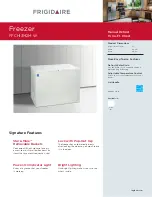
FFFC05M2K W
Brand: Frigidaire Pages: 9

FFCS0522AW
Brand: Frigidaire Pages: 11

FFCH16M5QWA
Brand: Frigidaire Pages: 16

FFCL2042AW
Brand: Frigidaire Pages: 16

FFCL1542AW
Brand: Frigidaire Pages: 17

FFC7C4AW0
Brand: Frigidaire Pages: 24

IHC-27
Brand: Master Bilt Pages: 16
FFCH13M2MW
Brand: Frigidaire Pages: 3
FFCH13M2MW
Brand: Frigidaire Pages: 11

216902400 (0212)
Brand: Kenmore Pages: 28

21501
Brand: Kenmore Pages: 6

HF11CM10NW
Brand: Haier Pages: 1

3T
Brand: sorin Pages: 96

FTE 2145 WW8E
Brand: Goddess Pages: 76

CHC12
Brand: Campomatic Pages: 9

Stoddart AXF.UC.1
Brand: AIREX Pages: 20


