61
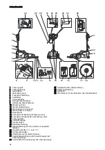
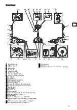
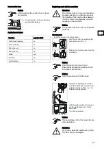
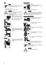
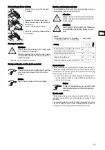
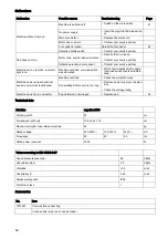
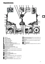
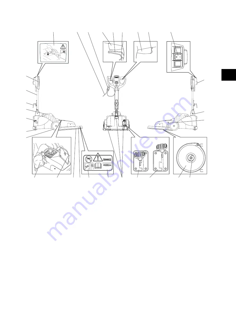
Structural layout
1 Machine handle
2 Steel guide bar
3 Cable hook
4 Motor cover
5 Foot pedal tool
6 Support wheels
7 Transport wheels
8 One-way fleece dust bag
9 Cover of dust bag container
10 Tool (pad)
11 Tool cover
12 Warning for transportation
13 Warning for pad type
14 Protecting profile
15 Foot pedal parking position (tool above)
16 Foot pedal working position (tool below)
17 Driving disc
18 Pad fixation
19 Suction hose
20 Cable passage
21 Cable routing (for UK and NA with special plug)
22 Main switch (ON = I /OFF = 0)
23 Safety switch
24 Right operating lever (motor ON/OFF)
25 Adjusting lever (for free moving of the steel guide
bar)
26 Adjusting lever for steel guide bar inclination
27 Left operating lever (motor ON/OFF)
28 Cord support
29 Main cord
30 Warning for the insertion of the fleece dust bag
1
2
3
4
5
6
7
8
15
16
17
20
19
21
22
23
24
26 25
27
28
29
30
18
10 11
14
HIGH SPEED PAD
min.
2000 rpm
PAD
12
13
9
EN

