background image

GTS

Technical Manual

9. April 2021

Edition: V1.00/2021

5-46

Copyright © 2020, Diversey

05

.3

2.

16

 d

riv

un

it 

en

co

de

r -

 2

10

ic

ro

_3

50

ic

ro

_V

1.

10

.fm

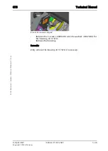
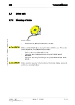
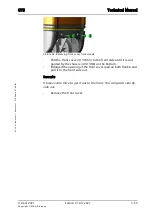
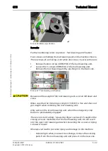
Picture 69: Encoder magnet

Remove the 3 screws (4006410) and the washers (4007440) for 

the housing (4131524).

Remove the housing.

Remarks

Only remove the housing (4131524) if necessary.

Summary of Contents for AERO 3500 micro

Page 1: ...Edition V1 00 2021 Technical Manual ...

Page 2: ...4 Technical data 4 1 Machine range 1 4 2 Technical information 2 4 2 1 Machine profile 2 4 2 2 Technical data 2 4 2 3 Machine speed 3 4 2 4 Dimensions and weights 3 4 2 5 Battery 4 4 2 5 1 Battery compartment 4 4 2 5 2 Battery specifications 5 4 2 6 Charger 6 4 2 7 Brush system 6 4 2 8 Suction power 7 4 2 9 Additional 7 4 3 Accessories Additional parts 8 4 3 1 Accessories 8 4 3 2 Additional parts ...

Page 3: ...tool lowering unit 31 5 6 2 Mounting of tool lowering unit 33 5 6 3 Removing of tool lowering offset 35 5 6 4 Mounting tool lowering offset 37 5 6 5 Removing of brush motor for offset 38 5 6 6 Mounting of brush motor for offset 39 5 6 7 Removing of linear drive 40 5 6 8 Mounting of linear drive 41 5 7 Drive unit 43 5 7 1 Removing of drive wheel 43 5 7 2 Mounting of drive wheel 44 5 7 3 Removing of...

Page 4: ... Connections 22 6 5 Hall sensor 24 6 5 1 Description 24 6 5 2 Removing of hall sensor steering angle 25 6 5 3 Mounting of hall sensor steering angle 26 6 5 4 Removing of hall sensor throttle 28 6 5 5 Mounting of hall sensor throttle 29 6 6 Main relay 30 6 6 1 Removing of main relay 30 6 6 2 Mounting of main relay 31 6 6 3 Removing of drive relay 32 6 6 4 Mounting of drive relay 33 6 7 Error codes ...

Page 5: ...9 April 2021 Edition V1 00 2021 Copyright 2020 Diversey Technical Manual 1 Forward ...

Page 6: ...he technical training 1 2 Technical Training The Technical Training is addressed as reference book for the technical training sessions and will be distributed to the floor care responsible and or to the technical training re sponsible after attending a training session provided by GTS max 2 persons per coun try The intension is that after this session a technical trainer is able to perform technic...

Page 7: ...d from TASKI spares documents 1 4 Summary We are convinced that the Technical Manual concept together with the Technical Training are powerful tools which will help our service organisations to achieve a higher level of quality in repairs and customer satisfaction If you have any comments or questions do not hesitate to contact your country respon sible Sincerely yours GTS Team ...

Page 8: ...9 April 2021 Edition V1 00 2021 Copyright 2020 Diversey Technical Manual 2 Elementary ...

Page 9: ... are used in this machine please carefully read the product label and Ma terial Safety Data Sheet MSDS Empty water tanks prior to carrying out any maintenance Ensure contaminated water is emptied into an approved drain Avoid pollution 2 2 ESD Static electricity is electricity at rest or the accumulation of electric charge as opposed to an electric current which is the movement of electricity The f...

Page 10: ...ersonal life These problems can be as simple as the shock resulting from walking across a carpet as costly as the destruction of sensitive electronic components Almost any material can generate static electricity The ability to store or unload the charge depends on the type of material Static discharge can damage devices this can result in immediate product failure or in a latent failure Latent fa...

Page 11: ...9 April 2021 Edition V1 00 2021 Copyright 2020 Diversey Technical Manual 3 General ...

Page 12: ...roper steps and or use of the part Failure to follow these instructions may result in faults Service This sign designates important information on grease lubricant and adhesive gluing points Failure to follow these instructions may result in faults Adjustment This sign designates important information on the correct tightening torque and positioning of the part It includes instructions for the wor...

Page 13: ...chnical Manual or TASKI spares Use ball bearing grease when ever mentioned in the Technical Manuel and TASKI spares 3 1 4 Direction description On the RH always means on the right hand side of the machine in working direction when you are standing behind the machine On the LH always means on the left hand side of the machine in working direction when you are standing behind the machine 3 1 5 Power...

Page 14: ...equired e g Set of fork spanners Set of Allen keys Set of Torx keys Set of pliers Set of circlip pliers Backing out punch set Rubber and steel hammer Set of screwdrivers flat and Phillips Socket set Torque wrench 0 25Nm Scissor jack 3 2 2 Material No special tools are required The above listings are only a recommendation for the technical training or working on the machine ...

Page 15: ...9 April 2021 Edition V1 00 2021 Copyright 2020 Diversey Technical Manual 4 Technical data ...

Page 16: ... Technical data 4 1 Machine range SKU Description Version Series 7524870 TASKI AERO 3500µicro BMS EURO SEV 01 7524871 TASKI AERO 3500µicro 01 7524899 TASKI AERO 3500µicro BMS UK 01 Table 1 Machine range Remarks For detailed SKU s overview please refer to your local marketing department The battery has to be ordered separately ...

Page 17: ...orking width incl side brush mm 650 Dust bag capacity l 15 Debris hopper capacity l 3 Table 2 Machine profile Pos Unit Value Noise level dB A 70 Vibration m s2 0 4 Approvals CB Nominal consumption W 1300 Power drive motor W 500 Power suction motor when cleaning W 300 Voltage V 24 Battery capacity max maintenance free Ah C5 180 Battery autonomy max 180 Ah maintenance free battery h 4 Internal charg...

Page 18: ...aning 2 0 Ramp max transport 10 Table 4 Machine speed Pos Unit Value Dimensions L W H mm 1350 650 1280 Door pass through with lifted up side brush mm 650 580 Battery compartment L W H mm 390 x 500 x 280 270 Net weight without batteries empty tank kg 181 Weight ready to use kg 305 Max floor pressure front N mm2 0 41 Max floor pressure rear N mm2 0 71 Turn radius between two walls mm 1800 Wheel diam...

Page 19: ...on V1 00 2021 4 4 Copyright 2020 Diversey 04 1 AERO 3500µicro technical data_V1 00 fm Picture 1 Dimensions 4 2 5 Battery 4 2 5 1 Battery compartment Pos Unit Value Battery compartment L W H mm 390 x 500 x 280 270 Table 6 Battery compartment ...

Page 20: ...ries use our preferred partner Relion Non BMS BMS machines can be set to the necessary charging curve Please adjust to the type of batteries you use For the correct connection of the batteries pay attention to the voltage of each battery and the correct connection Therefore refer to TASKI spares Supplier Type Voltage Ah C5 Length mm Width mm Height mm Weight kg Excide Sonnenschein GF106180V 6 180 ...

Page 21: ... Hz 50 60 Secondary V 24 Secondary A 25 Protection class BMS model I Approval CB cUL KC RCM Cable length BMS cable m 5 Table 8 Charger Pos Unit Value Main brush system mm 2 x 512 x 100 Main brush motor W 750 Main brush speed hard floor carpet rpm 900 1250 Brush pressure max N cm2 0 43 Side brush system mm 300 Side brush motor W 60 Side brush speed rpm Side broom offset mm 100 Table 9 Brush system ...

Page 22: ...04 1 AERO 3500µicro technical data_V1 00 fm 4 2 8 Suction power 4 2 9 Additional Pos Unit Value Vacuum motor W 300 Max air flow l s 16 Max vacuum mbar 110 Max vacuum kPa 11 Table 10 Suction power Pos Unit Value HEPA filtration optional H13 Hand tool hose mm 2500 Table 11 Additional ...

Page 23: ...pack of 5 3500µicro 7524880 Filter cloth pack of 5 3500µicro 7524873 HEPA filter H13 1pc 3500µicro Table 12 Accessories SKU Article Machine 7524874 Mop Box Support 3500µicro 7524875 Tool Holder Base 2100µicro 4122500 Wheel 200 front 2100µicro 4131705 Wheel 200 50 brown front 2100µicro 4131706 Wheel 200 50 red front 2100µicro 4131238 Drive wheel grey 2100µicro 4131703 Drive wheel brown 2100µicro 41...

Page 24: ...9 April 2021 Edition V1 00 2021 Copyright 2020 Diversey Technical Manual 5 Mechanical ...

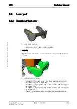
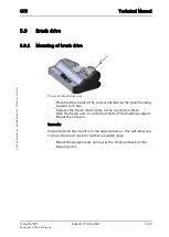
Page 25: ...ver Remove all accessories and disconnect the hoses from the tank cover 4134109 Open the tank cover Loosen the screw 4122639 at the lower side of the tank cover 4134109 Remove the tilt support cord 4134313 Close the tank cover Remove the two hinge bolts 4132661 Remove the tank cover 4134109 According to what you need to exchange remove the existing parts from the tank cover and place it on the new...

Page 26: ...nk cover Assemble the tank cover locking plate 4134111 at the end of this sequence Position the tank cover Mount the two hinge bolts Open the tank cover Position the tilt support cord 4134313 and tighten the screw Close the tank cover Place all accessories and hoses onto the tank cover Remarks Make sure that the tank cover sealing 4122621 is positioned properly is in a good condition and sealing t...

Page 27: ...ure 1 Vacuum motor Open the tank cover 4134109 Remove the filter cloth 7524880 togheter with the holding frame 4134114 Remove the four screws 4122639 together with the inlet protection 4134116 Remove the four screws 4134313 to release the vacuum motor fixation Picture 2 Vacuum motor fixation screws Remove the seat cover according to chapter REMOVING OF DRIVER SEAT COVER ...

Page 28: ...Disconnect the vacuum motor cables from the connection block 4047400 and 4047410 Remove the two screws 4122639 from the connection support plate 4134149 and lay it to the side Picture 3 Vacuum motor assembly Remarks For a better access to the vacuum motor cut the cable ties for the fixation of the suction hose left and right Remove the vacuum assembly by pulling it out from the tank Picture 4 Vacu...

Page 29: ...Remarks Carefully remove the vacuum motor cover as you can damage the wires of the thermo switch Remove the upper 4134085 and the surrounding 4134084 noise absorbing mat Remove the two screws 4122639 from the vacuum motor holder 4134089 Remove the vacuum motor holder Remove vacuum motor sealing 4134088 Remove the vacuum motor 4134053 Remarks Remove the vacuum motor cable from the cover by pulling ...

Page 30: ...6 of the vacuum motor into the suction housing 4134086 Build in the vacuum motor Position the vacuum motor sealing ring Remarks Ensure that the vacuum motor sealing is properly positioned before assembling vacuum motor assembly Assemble vacuum motor holder Place the two noise absorbing mats Carefully thread in the vacuum motor cables through the cover grommet Place the cover on to the housing an m...

Page 31: ...e of the tank Place the inlet protection plate and mount the 4 screws Place the filter cloth together with the holding frame Close the tank cover Position the connection support plate and mount the two screws Connect the vacuum motor wires to the connection block Mount the seat cover according to chapter MOUNTING OF DRIVER SEAT COVER Remarks If you have to remove cable ties then position the new o...

Page 32: ...ch 3500µicro_V1 00 fm 5 2 Tank 5 2 3 Removing of cleaning mode micro switch Picture 9 Cleaning mode micro switch Remove the four screws 4122639 from the micro switch cover 4134106 Disconnect the plug from the micro switch 4133638 Remove the screw 4070960 together with the washer 4091230 Remove the micro switch 4133638 ...

Page 33: ...aning mode micro switch Picture 10 Mounting micro switch Position micro switch into the cover Mount the washer and screw Connect the plug from the micro switch Place the micro switch cover onto the tank 4134108 and mount the screws Picture 11 Micro switch details After working on the micro switch check the functionality of the correct switching of the two cleaning modes ...

Page 34: ...move the tank cover according to chapter REMOVING OF TANK COVER Remove the seat cover according to chapter REMOVING OF DRIVER SEAT COVER Remove the vacuum motor assembly according to chapter REMOVING OF VAVCUUM MOTOR ASSEMBLY Disconnect all plugs and connectors to the tank Remove the 6 fixation screws 4109990 of the tank 4134108 at the 2 supports 4131414 Remarks To reach the 6 fixation screws 4109...

Page 35: ...1 5 11 Copyright 2020 Diversey 05 70 18 tank tank 3500µicro_V1 00 fm Picture 13 Removing recovery tank Lift out the whole tank from the lower part According to what you need to exchange remove the existing parts from the tank and place it on the new one ...

Page 36: ...ount the 6 fixation screws of the tank at the 2 supports Mount the vacuum motor assembly according to chapter MOUNTING OF VAVCUUM MOTOR ASSEMBLY Mount all plugs and connectors to the tank Mount the seat cover according to chapter MOUNTING OF DRIVER SEAT COVER Picture 15 Recovery tank fixation Mount the whole tank cover according to chapter MOUNTING OF TANK COVER Place all accessories and hoses ont...

Page 37: ...e position for example onto the floor beside the machine Place the driver seat on a stable position Remove the seat cover according to chapter REMOVING OF DRIVER SEAT COVER Remarks To reach the driver seat fixation you need to remove the two rear batteries Disconnect the driver seat cable wires from the connection block 4122096 Picture 17 Removing driver seat Cut the cable ties and thread out the ...

Page 38: ...t 3500µicro_V1 00 fm 5 3 Driver seat 5 3 2 Mounting of driver seat Picture 18 Driver seat unit Place the seat on a stable position Thread in the cable Connect the driver seat cable wires to the connection block Picture 19 Mounting driver seat Mount the seat cover according to chapter MOUNTING OF DRIVER SEAT COVER ...

Page 39: ...ver seat 4132166 is constructed that you can move it around We advise to place it on a stable position for example onto the floor beside the machine Place the driver seat on a stable position Unlock the seat cover lock 4129284 Picture 21 Removing driver seat cover Remove the driver seat cover 4131363 by lifting it up According to what you need to exchange remove the existing parts from the driver ...

Page 40: ...cover 3500µicro_V1 00 fm 5 3 Driver seat 5 3 4 Mounting of driver seat cover Picture 22 Driver seat cover unit Position the driver seat cover Make sure you do not squeeze anything e g cables when positioning the driver seat cover Picture 23 Mounting driver seat cover Position the driver seat Lock the seat cover lock ...

Page 41: ...ver seat 4132166 is constructed that you can move it around We advise to place it on a stable position for example onto the floor beside the machine Place the driver seat on a stable position Remove the two screws 4122639 from the cover 4132165 Remove the cover Picture 25 Removing seat switch Turn the seat switch set 4121900 anti clockwise to release it Disconnect the wires from the seat switch Re...

Page 42: ... unit Position the seat switch into the mounting hole Connect the wires to the seat switch Turn the seat switch set clockwise until it is fixated correctly Position the cover Position and tighten the two screws Picture 27 Mounting seat switch Place the driver seat onto the driver seat cover Make sure that you check the correct function of the seat switch during each visit as this is a security fea...

Page 43: ...refer to Electrical section Remarks When using the option IntelliTrail then you need to remove it first For this instruction please refer to the separate TASKI IntelliTrail mounting instructions in TASKI spares Remove the 6 screws 4109990 for the cover 4131489 Remove the cover Remove the 2 screws 4052060 for the fixation of the holder plate 4131690 Remove the 4 screws 4109990 which fixate the hold...

Page 44: ...emoving front hood details Remarks It is only necessary to loosen the upper connection of the Cardan joint Lift out the steering pipe 4131504 from the Cardan joint Lift off the whole front hood with the remaining parts on it Tank care of the cables connectors and hose inside the steering support 4131371 lifting off the front hood from the machine According to what you need to exchange remove the e...

Page 45: ...nectors and hose inside the steering support 4131371 positioning the front hood on the machine Picture 32 Mounting front hood Position the steering pipe into the Cardan Joint Tighten the self locking nut and screw of the Cardan joint Position the holder plate and mount the 4 screws which fixate the holder plate and the front hood Mount the 2 screws for the fixation of the holder plate to the steer...

Page 46: ...V1 00 fm Remarks When using the option IntelliTrail then you need to mount it again For this instruction please refer to the separate TASKI IntelliTrail mounting instructions in TASKI spares Complete assembling according to chapter MOUNTING OF DASHBOARD Make sure that the indication and warning signs are on the front hood ...

Page 47: ...cover according to chapter REMOVING OF FRONT COVER Loosen the 4 self locking nuts 4031060 of the steering unit 4131239 Untighten the 2 tension screws 4006520 counter clock wise to release tension of the steering roller chain 4131862 Remove the clip of the chain joint 4122221 Remarks The steering roller chain clip is at the bottom side of the chain Remove the chain joint of the steering roller chai...

Page 48: ... Position the steering roller chain onto the chain wheels Mount the chain joint Remarks Mount the chain joint from the upper side so that the clip is on the bottom side Mount the clip of the chain joint Tension the steering roller chain with the 2 tension screws Make sure you do not tension the steering roller chain too much Tighten the 4 self locking nuts of the steering unit Mount the front cove...

Page 49: ...hind of the traction wheel to ensure that the machine does not move Lift the front of the machine with a jack Make sure you position the jack on the chassis or the steering unit and not on the bottom part plastic Remove the screw and the washer of the front wheel Remove the front wheel by pulling it off the axle Remarks The part number of the front wheel can vary as we have different types Wheel 4...

Page 50: ...wheel 3500µicro_V1 00 fm 5 4 Steering unit 5 4 6 Mounting of front wheel Picture 36 Mounting front wheel Position the front wheel on the axle Mount and tighten the screw and the washer Service Lubricate the front wheel bearing with ball bearing grease 4039680 Apply adhesive locking 4017370 on the hexagon screws ...

Page 51: ...over Remove the 3 screws 4006430 of the pedal support 4131521 Picture 38 Removing pedal unit Remove the complete pedal from the chassis Remarks You can either thread it to the bottom or to the top for easier access Remove the screw 4042640 of the axle 4131528 Remove the axle 4131528 Remarks To remove the axle it can help to push the pedal 4131522 sideways Remove the pedal torsion springs 4129039 T...

Page 52: ...d mount the pedal torsion springs Position the pedal and fixate it with the axle Remarks When pressing both axles 4131527 4131528 together make sure that the pedal is nicely in the slot Mount the screw to fixate the 2 axles Position the pedal support and mount the 3 screws Position the foot plate Mount the two screws Remarks For replacing of hall sensor refer to the chapter REMOVING OF HALL SENSOR...

Page 53: ..._3500µicro_V1 10 fm 5 5 Pedals 5 5 3 Removing of pedal micro switch Picture 40 Pedal micro switch Remove the pedal unit according to chapter REMOVING OF PEDAL SPRING Disconnect the wires to the micro switch Remove the two screws 4067140 of the micro switch 4021120 Picture 41 Removing micro switch Remove the micro switch ...

Page 54: ...0µicro_V1 10 fm 5 5 Pedals 5 5 4 Mounting of pedal micro switch Picture 42 Micro switch unit Position the micro switch onto the pedal unit Picture 43 Mounting micro switch Mount and tighten the two screws for micro switch Connect the wires to the micro switch Complete assembling according to chapter MOUNTING OF PEDAL SPRING ...

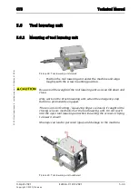
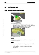
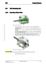
Page 55: ...t the plug of the linear drive 4127185 at the electronics 4131532 Remarks For correct position of the connections refer to chapter ELECTRONICS CONNECTIONS refer to Electrical section Picture 45 Tool lowering unit details Cut all cable ties for the fixation of the cables of the liner drive Thread out the cable of the linear drive Remove the retaining washer 4058370 of the metal rope holder 4134070 ...

Page 56: ... to the back side Picture 47 Tool lowering unit fixation Be aware of the weight of the tool lowering unit as it can fall down and close Make sure that the metal rope compl 4134183 is free and does not get caught when removing the tool lowering unit Only work on the brush lowering unit when the emergency stop button is permanently engaged There is a risk of cutting squeezing fingers seriously if ca...

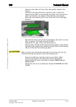
Page 57: ...he screw mounting position Be aware of the weight of the tool lowering unit as it can fall down and close Only work on the brush lowering unit when the emergency stop button is permanently engaged There is a risk of cutting squeezing fingers seriously if caught in the closing scissors mechanism of the tool lowering unit Do not reach into the open tool lowering unit when loosening the screws or try...

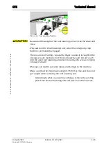
Page 58: ...position Mount the fixation screw of the tool lowering unit refer to screw No 1 in picture Tool lowering unit details Tighten all 4 screws of the tool lowering unit Thread in the ending of the metal rope trough the castor wheel Place the metal rope holder which is located on the tool lowering offset and mount the retaining washer Make sure that the metal rope and cable of the linear drive do not i...

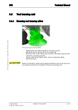
Page 59: ...emove the tool Lower the brush drive for easier access Disconnect the brush motor wires from the connection block 4082740 which is mounted on the chassis 4131386 Remove the retaining washer 4058370 from the bolt 4134070 of the metal rope 4134182 Remove the bolt out of the lowering unit Picture 52 Metal rope fixation Remove the three screws 4065050 of the tool lowering which fixates it onto the cha...

Page 60: ...nently engaged There is a risk of cutting squeezing fingers seriously if caught in the closing scissors mechanism of the tool lowering unit Do not reach into the open tool lowering unit when loosening the screws or trying to lower it down Missteps can lead to personal injury and damage to the machine Make sure that the metal rope compl 4134183 is free and does not get caught when removing the tool...

Page 61: ...e 54 Linear drive for offset Position the tool lowering offset onto the chassis Mount the three screws of the tool lowering Place the bolt of the metal rope onto the tool lowering unit and mount the retaining washer Connect the brush motor wires to the connection block Mount the tool Make sure that the metal rope compl and cable of the linear drive do not interfere with the movement of the tool lo...

Page 62: ...he brush drive for easier access Disconnect the brush motor wires from the connection block 4082740 which is mounted on the tool lowering support 4134076 Remove the screw 4006900 and countersunk washer 4134329 from the brush motor 4134077 Remove the coupling disc 4134078 by pulling it of the brush motor axle Picture 56 Brush motor coupling disc Remove the four screws 4006430 and washer 4007470 fro...

Page 63: ...the brush support plate Mount the four screws and washer onto the brush support plate Mount the coupling disc together with the screw and countersunk washer onto the brush motor axle Picture 58 Brush motor fixation Remarks Ensure that the feather key is mount the brush motor axle before assembling coupling disc Service Lubricate the motor axle with ball bearing grease 4039680 before mounting the c...

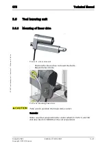
Page 64: ...to chapter REMOVING OF BRUSH DRIVE Remove the seat cover according to chapter REMOVING OF SEAT COVER Remove the tool lowering unit according to chapter REMOVING OF TOOL LOWERING UNIT Remove the two retaining washers 4058370 from the two bolts 4134068 and 4134067 of the linear drive 4127185 Remove the two bolts 4134068 and 4134067 to one side Picture 60 Removing linear drive Be aware of the tension...

Page 65: ... 5 6 Tool lowering unit 5 6 8 Mounting of linear drive Picture 61 Linear drive unit Position the linear drive to mount the bolts Mount the two bolts Picture 62 Mounting linear drive Take care to position the linear drive correct Remarks Make sure that you position the castor wheel 4134121 and the distance bush 4134066 at the correct position ...

Page 66: ...ining washer Thread in the cable and place Remarks Make sure that you fixate the cable with cable ties When fixating the cable of the linear drive make sure the necessary movement is allowed Mount the tool lowering unit according to chapter MOUNTING OF TOOL LOWERING UNIT Mount the brush unit according to chapter MOUNTING OF BRUSH DRIVE Mount the seat cover according to chapter MOUNTING OF SEAT COV...

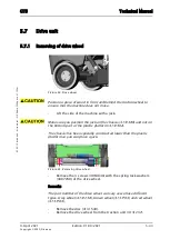
Page 67: ... jack Make sure you position the jack on the chassis 4131386 and not on the bottom part of the plastic platform 4131362 The chassis has been specially constructed lower than the plastic platform so you can place a jack Picture 65 Removing drive wheel Remove the 3 screws 4064840 with the spring lock washers 4007780 of the drive wheel Remarks The part number of the drive wheel can vary as we have di...

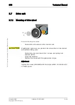
Page 68: ... 66 Mounting drive wheel Position the drive wheel on the traction unit If applicable make sure you position the drive wheel on the traction unit with the fitting side Position the disc and mount the 3 screws and spring lock washers with it Lower the machine Tighten the screws with the appropriate torque Adjustment Tighten the screws 4064840 with the torque 22Nm For details refer to TASKI spares ...

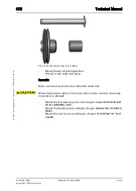
Page 69: ...pter REMOVING OF DRIVE WHEEL Remove the 3 screws 4062760 for the cover 4131525 Remove the cover Picture 68 Removing encoder Remove the rotary encoder 4131514 by lifting it off the housing 4131524 Thread out the cable of the rotary encoder Disconnect the rotary encoder at the electronics 4131532 Loosen the Allen screw for the magnet compl 4131543 Remove the magnet compl The magnet is only glued ont...

Page 70: ...46 Copyright 2020 Diversey 05 32 16 drive unit encoder 2100µicro_3500µicro_V1 10 fm Picture 69 Encoder magnet Remove the 3 screws 4006410 and the washers 4007440 for the housing 4131524 Remove the housing Remarks Only remove the housing 4131524 if necessary ...

Page 71: ...ghten the screw The magnet is only glued onto the bushing Take care when handling it Thread in the cable of the rotary encoder Connect the rotary encoder to the electronics Position the rotary encoder onto the housing Place the rotary encoder nicely onto the pins on the housing Picture 71 Encoder details Adjustment Make sure the screw for the magnet compl is in the center of the hole in the rotary...

Page 72: ...ion V1 00 2021 5 48 Copyright 2020 Diversey 05 32 16 drive unit encoder 2100µicro_3500µicro_V1 10 fm Picture 72 Encoder adjustment Position the cover and mount the 3 screws Mount the drive wheel according to chapter MOUNTING OF DRIVE WHEEL ...

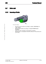
Page 73: ...3500µicro_V1 10 fm 5 7 Drive unit 5 7 5 Removing of brake Picture 73 Brake Remove the drive wheel according to chapter REMOVING OF DRIVE WHEEL Remove the encoder according to chapter REMOVING OF ENCODER Disconnect the connector of the brake 4132164 Remove the 3 screws which fixate the brake to the traction unit 4131237 ...

Page 74: ...n the brake and mount the 3 screws Make sure that the brake is nicely in center with the axle This needs to be considered for mounting the encoder Connect the connector of the brake Complete assembly according to chapter MOUNTING OF ENCODER Complete assembly according to chapter MOUNTING OF DRIVE WHEEL Make sure that you check the function of the brake during each visit as this is a security featu...

Page 75: ...the squeegee Remove the drive wheel LH and RH according to chapter REMOVING OF DRIVE WHEEL Remove the rotary encoder according to chapter REMOVING OF ENCODER Remarks If you only remove the rotary encoder then you do not have to thread out the cable to the electronics Disconnect the wires of the drive unit compl 4131237 from the connection block 4108420 Disconnect the connector of the brake Remove ...

Page 76: ...nit drive unit 3500µicro_V1 00 fm Picture 76 Removing drive unit Push the drive unit to the front to slide it out of the chassis Picture 77 Removing drive unit compl Remove the drive unit According to what you need to exchange remove the existing parts from the drive unit and place it on the new one ...

Page 77: ... chassis Position and mount the 4 hexagon screws for the drive unit to the chassis on the LH side Position and mount the 4 hexagon screws for the drive unit to the chassis on the RH side Picture 79 Mounting drive unit Connect the connector for the brake Connect the wires of the drive unit to the connection block Mount the rotary encoder according to the chapter MOUNTING OF ENCODER Mount the drive ...

Page 78: ...he foot cover Disconnect the wires for the LED strap 4131265 at the connection block 4047420 Remove the hexagon screw 4016140 the washer 4110070 and the self locking nut 4007340 on the RH side Remove the hexagon screw 4016140 the washer 4110070 and the self locking nut 4007340 on the LH side Picture 81 Removing front cover Remove the 2 covers 4131868 for the 2 hexagon screws 4069420 at the front R...

Page 79: ...Removing front cover front screws Pull the front cover 4131665 to the front side until it is not guided by the chassis 4131386 on the bottom Enlarged the opening of the front cover pull on both flanks and pull it to the front side out Remarks It takes some force to get it out to the front You can pull it side by side out Remove the front cover ...

Page 80: ...nto the chassis Remarks It takes some force to get it on to the front You can push it side by side in Picture 84 Mounting front cover Mount the 2 hexagon screws and the 2 washers at the front Mount the 2 covers at the front Mount the hexagon screw the washer and the self locking nut on the LH side Mount the hexagon screw the washer and the self locking nut on the RH side Connect the wires for the ...

Page 81: ...y 05 42 21 lower part front cover 3500µicro_V1 00 fm Place the foot cover and mount the 2 screws Adjustment The 2 screws 4109990 on the left and the right flank of the front cover are for adjustment to align the front cover and the platform 4131362 Picture 85 Front cover adjustment ...

Page 82: ...er the brush deck Leave it in the upper position This will allow you to pivot the brush deck for further disassembly steps Picture 87 Remove pressure spring Remove the two pressure springs 4130351 at the front and back of the lowering unit Remarks To remove the pressure springs you need to tilt the brush deck to the back side then to the front side This will allow the two pressure springs to be pu...

Page 83: ...ving hose and stop pin Remove the whole brush unit by pulling it off from the bolts of the brush holding support 4134069 Remarks Pull the brush unit to the right hand side so the bracket 41334049 comes off of the brush holding support 4134069 Disconnect the brush motor wires from the connection block 4082740 mounted on the chassis 4131386 Remarks You need to move the released brush unit to the sid...

Page 84: ...the brush unit in the correct position so the brush holding support is in line Connect the brush motor wires to the connection block Slide the brush unit on to the bolt bolts of the holding support Mount the stop pin Remarks Ensure that the brush unit is in the upper position This will allow you to pivot the brush deck for further assembly steps Mount the two pressure springs at the front and back...

Page 85: ...l 3500µicro_V1 00 fm Remarks To mount the pressure springs you need to tilt the brush deck to the back side then to the front side This will allow to place the two pressure springs in to the defined position Picture 91 Mounting pressure spring Make sure that the wires cannot be damaged during movements of the brush unit ...

Page 86: ... belt Remarks No need to remove the brush drive for the following disabling steps Else remove brush drive according to chapter REMOVING OF BRUSH DRIVE Remove the 3 screws 4132896 for the belt cover 4134091 Remove the belt cover Picture 93 Removing brush belt cover Untighten the 3 fixation nuts 4007270 of the brush motor 4130739 Remove the brush motor belt 4117030 as the tension is now released ...

Page 87: ...GTS Technical Manual 9 April 2021 Edition V1 00 2021 5 63 Copyright 2020 Diversey 05 68 23 brush drive brush belt 3500µicro_V1 00 fm Picture 94 Remove bush belt ...

Page 88: ...nit Position the brush belt carefully and tension the belt Remarks To tension the belt tighten the screw of the tension lever 4134268 with the appropriate torque Use a torque wrench to tighten the brush belt Adjustment Tighten the screws of the tension lever 4134268 with the torque of 4Nm For details refer to TASKI spares Tighten the 3 fixation nuts of the brush motor Picture 96 Brush belt adjustm...

Page 89: ... the brush motor 4130739 by hand to ensure that the belt is correctly mounted and stays in the middle of the pulleys Position the brush cover onto the brush drive Position and tighten the 3 screws of the brush cover If needed complete assembling according to chapter MOUNTING OF BRUSH DRIVE Remarks Ensure that the brush belt does not touch the cover ...

Page 90: ...h belt according to chapter REMOVING OF BRUSH BELT Remove the 3 nuts 4007270 from each bush coupling sets Remove the brush coupling set 4134043 or 4134044 The brush coupling set with the number 4133403 got grooves on it Please ensure that it is mounted onto the correct position therefore on the front side in driving direction Refer to the mounting picture as well as to TASKI spares According to wh...

Page 91: ...he inside of the bearings of the roller drive assembly 4134043 or 4134044 The roller drive with the number 4133403 got grooves on it Please ensure that it is mounted onto the correct position therefore on the front side in driving direction red arrow shows driving direction Refer to the enclosed picture as well as to TASKI spares Picture 99 Bush coupling set position Mount the 3 nuts to the roller...

Page 92: ...0 Diversey 05 68 43 brush drive brush coupling set 3500µicro_V1 00 fm Make sure that you check the function of the coupling hubs 4134040 on the machine as well as on the tool during each visit This to ensure that they engage and stay in place Picture 100 Bush coupling hubs ...

Page 93: ...Picture 101 Brush motor Remarks To get better access to the brush motor remove the brush from the machines Remove the brush drive according to chapter REMOVING OF BRUSH DRIVE Remove brush belt according to chapter REMOVING OF BRUSH BELT Remove the 3 fixation nuts 4007270 and washers 4031330 of the brush motor 4130739 Picture 102 Fixation brush motor Remove the brush motor 4130739 ...

Page 94: ...ips of the cover The belt pulley 4134050 of the brush motor got a separate ordering number It has to be ordered separately and does not come wit the brush motor Mount the belt pulley 4134050 onto the brush motor Remarks Fixate the motor axle with a 10mm fork wrench on the top side Us a 19mm fork wrench to tighten the belt pulley onto the motor axle Position the brush motor Mount the 3 washers and ...

Page 95: ...unting belt pulley Remarks Ensure that the cables of the motor are positioned that they lead directly to the connection block Adjustment Shorten the brush motor cables to approx 200mm This will ensure a sufficient length to the connection block Make sure that the cables of the brush motor do not interfere with the movement of the tool lowering unit ...

Page 96: ...9 April 2021 Edition V1 00 2021 Copyright 2020 Diversey Technical Manual 6 Electrical ...

Page 97: ...cs The dashboard visualises the states of the machine It also functions as a connection between the electronics and the devices e g hall sensor key switch and foil keyboard Applying the correct torque where required is essential for a safe operation of the machine ESD can harm the electronic boards and therefore reduce the life time of the machine Use always an ESD bag to protect them 6 1 2 System...

Page 98: ... turning the key 4130800 to the Start position similar known as with cars When the key switch is turned to the Start position then it activates the micro switch 4124476 and feeds the electronics with power The electronics get power and it enables the processor to start and go into the self holding Afterwards the key falls back into the position 1 and keeps the micro switch activated The electronic...

Page 99: ... separate emergency loop which contains following elements Stop actuator Charger internal switch OR battery connector switch 4131559 Start up Self holding The emergency loop controls the main relay 2100µicro 4127063 4000 5000 4129311 3500µicro 4134244 Only when the complete emergency loop is closed the main relay is active and the power supply is ensured Picture 3 Start up Self holding ...

Page 100: ...nge the position of the steering wheel for better access to the screws if needed Remove the 6 screws 4127073 of the dashboard set 4134599 Picture 5 Removing dashboard Remove the dashboard from the front hood 4131360 Be cautious when removing the dashboard as you can damage the wires or the ribbon cables of the dashboard Disconnect all electrical connections to dashboard Remove the dashboard ...

Page 101: ...shboard Position the dashboard Connect all electrical connections to the dashboard Position the dashboard onto the front hood Be cautious when mounting the dashboard as you can damage the wires or the ribbon cables of the dashboard Mount the 6 screws of the dashboard Make sure that you check the function of the stop actuator during each visit as this is a security feature ...

Page 102: ...V2 00 fm 6 2 Dashboard 6 2 3 Connections Picture 7 Dashboard connections Picture 8 Dashboard key switch Please find description of the connections on the following table The connections are marked in the upper pictures Picture Dashboard connections and Dashboard key switch with numbers and the pin 1 of the connections is marked with a red dot ...

Page 103: ...tion charge failed red 2 X2 Charger communication 4 Immobilise OUT Emergency loop 2 X2 Charger communication 5 Immobilise IN Emergency loop 2 X2 Charger communication 6 GND 3 X3 Stop actuator 1 Emergency loop IN 3 X3 Stop actuator 2 Emergency loop OUT 4 X4 Start switch 1 Start IN 4 X4 Start switch 2 Start OUT 5 X5 Control unit 1 Emergency loop 5 X5 Control unit 2 Coding 1 TASKI swingo 4000 5 X5 Co...

Page 104: ... keypad right 5 Not connected 7 X20 Membrane keypad right 6 Not connected 7 X20 Membrane keypad right 7 SCAN OUT 3 7 X20 Membrane keypad right 8 SCAN OUT 4 7 X20 Membrane keypad right 9 MUX OUT 0 7 X20 Membrane keypad right 10 MUX OUT 1 7 X20 Membrane keypad right 11 MUX OUT 2 7 X20 Membrane keypad right 12 MUX OUT 3 7 X20 Membrane keypad right 13 MUX OUT 4 7 X20 Membrane keypad right 14 MUX OUT 5...

Page 105: ... keypad right 24 Not connected 8 X21 Membrane keypad left 1 SCAN OUT 0 8 X21 Membrane keypad left 2 SCAN OUT 1 8 X21 Membrane keypad left 3 SCAN OUT 2 8 X21 Membrane keypad left 4 MUX OUT 0 8 X21 Membrane keypad left 5 MUX OUT 1 8 X21 Membrane keypad left 6 MUX OUT 2 8 X21 Membrane keypad left 7 MUX OUT 3 8 X21 Membrane keypad left 8 MUX OUT 4 8 X21 Membrane keypad left 9 MUX OUT 5 8 X21 Membrane ...

Page 106: ...embrane keypad left 21 TASTER IN 3 8 X21 Membrane keypad left 22 TASTER IN 0 8 X21 Membrane keypad left 23 TASTER IN 1 8 X21 Membrane keypad left 24 TASTER IN 2 Key switch Dashboard key switch micro switch 1 Micro switch OUT key switch Key switch Dashboard key switch micro switch 2 Micro switch IN start switch Key switch Dashboard key switch micro switch 3 Micro switch OUT start switch Key switch ...

Page 107: ...moving of electronics Picture 9 Electronics Remove the seat cover according to chapter REMOVING OF DRIVER SEAT COVER refer to Mechanical section Disconnect the wires and the connectors from the electronics 4131532 Loosen the 4 screws 4122523 to remove the electronics from the electrical support 4131385 Picture 10 Removing electronics Remove the electronics ...

Page 108: ...ition the electronics onto the electrical support Position and tighten the 4 screws Connect the wires and the connections to the electronics Tighten the connectors with the correct torque Refer to adjustment and TASKI spares Complete assembling according to chapter MOUNTING OF DRIVER SEAT COVER refer to Mechanical section Adjustment M5 with 6 Nm GND drive brush vac minus M6 with 8 Nm 24V drive bru...

Page 109: ...µicro_4000_5000_3500µicro_V2 00 fm 6 3 Electronics 6 3 3 Connections Picture 12 Electronics connections Please find description of the connections on the following table The connections are marked in the upper picture Picture Electronics connections with numbers and the pin 1 of the connections is marked with a red dot ...

Page 110: ...sh 1 Motor 1 Minus 7 X7 Brush 2 Motor 1 Plus TASKI swingo 4000 5000 TASKI AERO 3500µicro Side brush 8 X8 Brush 2 Motor 1 Minus TASKI swingo 4000 5000 TASKI AERO 3500µicro Side brush 9 X9 Vac Vacuum motor 1 Plus TASKI AERO 3500µicro Not connected 10 X10 Vac Vacuum motor 1 Minus 11 X70 USB host Type A 1 VBUS 11 X70 USB host Type A 2 D Minus 11 X70 USB host Type A 3 D Plus 11 X70 USB host Type A 4 GN...

Page 111: ...Trail 16 X23 Drain pump 1 SWP TASKI swingo 4000 5000 Option TASKI AERO 3500µirco Reversing light white 16 X23 Drain pump 2 SWP TASKI swingo 4000 5000 Option TASKI AERO 3500µirco Reversing light white 17 X24 Flash Warning light 1 WL 17 X24 Flash Warning light 2 WL 18 X25 Lamp Front light 1 SW 18 X25 Lamp Front light 2 SW 19 X26 Pump 1 1 FWP_1 TASKI AERO 3500µicro Not connected 19 X26 Pump 1 2 FWP_1...

Page 112: ...22 X30 Relay Main relay 1 MainRel 22 X30 Relay Seat switch 2 Seat 22 X30 Relay Drive relay 3 DriveRel 22 X30 Relay Main relay 4 MainRel 22 X30 Relay Seat switch 5 Seat 22 X30 Relay Drive relay 6 DriveRel 23 X40 Dig Input Throttle micro switch 1 DIG_EIN_1A 23 X40 Dig Input Reserve 1 2 DIG_EIN_2A TASKI AERO 3500µicro Hand tool 23 X40 Dig Input Reserve 2 3 DIG_EIN_3A TASKI AERO 3500µicro Pressure swi...

Page 113: ...e 2 GND 24 X43 Brush pres Signal brush lowering drive 3 Not connected 24 X43 Brush pres Signal brush lowering drive 4 Not connected 24 X43 Brush pres Signal brush lowering drive 5 Output Signal 24 X43 Brush pres Signal brush lowering drive 6 Not connected 25 X42 Steering Hall sensor steering angle 1 Plus 5VDC 25 X42 Steering Hall sensor steering angle 2 GND 25 X42 Steering Hall sensor steering ang...

Page 114: ...Coding 1 TASKI swingo 4000 27 X51 Control unit 3 Coding 2 TASKI swingo 5000 27 X51 Control unit 4 Coding 3 TASKI swingo 2100µicro 27 X51 Control unit 5 Coding 4 TASKI AERO 3500µicro 27 X51 Control unit 6 Not connected 28 X60 Charger 1 GND 28 X60 Charger 2 Plus 12VDC 28 X60 Charger 3 Not connected 28 X60 Charger 4 Battery detection 28 X60 Charger 5 Battery charge detection 28 X60 Charger 6 I2C SCL ...

Page 115: ...30 X45 Waste water Sensor 4 SWS_IN Signal TASKI swingo 4000 5000 31 X44 Fresh water Sensor 1 Plus 24VDC TASKI swingo 4000 5000 31 X44 Fresh water Sensor 2 Not connected TASKI swingo 4000 5000 31 X44 Fresh water Sensor 3 GND TASKI swingo 4000 5000 31 X44 Fresh water Sensor 4 SWS_IN Signal TASKI swingo 4000 5000 32 X46 Encoder 1 Plus 12VDC 32 X46 Encoder 2 GND 32 X46 Encoder 3 CHA 32 X46 Encoder 4 C...

Page 116: ...ttery connector 4043320 Disconnect the plug to the main cord fixated on the charger holder 4131448 Disconnect the plug of the cable 4131707 to the electronics 4131532 Disconnect the plug of the cable 4131558 to the dashboard 4134599 Remove the 2 screws 4006430 for the charger holder 4131448 Remove the charger holder with the charger out of the electrical support 4131385 by sliding it upwards Pictu...

Page 117: ...nting charger Slide the charger holder with the charger onto the electrical support Mount the 2 screws for the charger holder Connect the plug of the cable to the dashboard Connect the plug of the cable to the electronics Connect the plug to the main cord Remarks Fixate the plugs with cable ties onto the charger support as they have also the function of a tension release Connect the battery connec...

Page 118: ...ions 2100µicro_3500µicro_V2 00 fm 6 4 Charger 6 4 3 Connections Picture 17 Charger connections Please find description of the connections on the following table The connections are marked in the upper picture Picture Charger connections with numbers and the pin 1 of the connections is marked with a red dot ...

Page 119: ... electronics 4 Battery detection 4 Communication to electronics 5 Battery change detection 4 Communication to electronics 6 I2C SCL 4 Communication to electronics 7 I2C SDA 4 Communication to electronics 8 Battery change detection input reset 5 Communication to dashboard 1 Not connected 5 Communication to dashboard 2 Not connected 5 Communication to dashboard 3 Immobiliser internal switch 5 Commun...

Page 120: ...fers to the potential difference Hall voltage on opposite sides of a thin sheet of conducting or semiconductor material in the form of a Hall bar or a van der Pauw element through which an electric current is flowing created by a magnetic field applied perpendicular to the Hall element Edwin Hall discovered this effect in 1879 Source http www answers com topic hall effect Picture 18 Hall effect ...

Page 121: ...to Mechanical section Remove the 2 screws 4129073 of the foot cover 4131666 Remove the foot cover Disconnect the cable for the hall sensor steering angle 4131503 at the electronics 4131532 Thread out the cable Remove the screw 4087930 for the LH cover 4131686 Remove the cover Remove the screw 4087930 for the RH cover 4131687 Remove the cover Remove the 2 screws 4122950 for the hall sensor holder 4...

Page 122: ...t the correct hall sensor for the steering angle Position and tighten the 2 self locking nuts Picture 22 Mounting hall sensor steering angle Position the hall sensor holder and mount the 2 screws Position the covers on the LH and RH side and mount the screws Thread in the cable for the hall sensor steering angle Connect the cable to the electronics Place the foot cover and mount the 2 screws Compl...

Page 123: ...06 22 19 hall sensors steering angle 3500µicro_V1 00 fm Remarks If in any case the hall sensor steering angle would not work correctly the machine would still run but only in a defined slower speed For error codes please refer to the chapter Error Codes or to the Service Tool Manual ...

Page 124: ...VER SEAT COVER refer to Mechanical section Remove the throttle according to chapter REMOVING OF PEDAL SPRING refer to Mechanical section Disconnect the cable for the hall sensor throttle 4131509 at the electronics 4131532 Thread out the cable Remove the 2 screws 4079170 and the 2 washers 4007440 from the hall sensor throttle Be aware of the parts mounted on the screw 4079170 as they can fall down ...

Page 125: ... correct hall sensor for the throttle Remarks Make sure that you position the 2 bushes 4131523 at the correct position Picture 26 Mounting hall sensor throttle Thread in the cable for the hall sensor throttle Connect the cable to the electronics Complete assembling according to chapter MOUNTING OF PEDAL SPRING refer to Mechanical section Complete assembling according to chapter MOUNTING OF DRIVER ...

Page 126: ... seat cover according to chapter REMOVING OF DRIVER SEAT COVER refer to Mechanical section Disconnect the wires and the plugs of the main relay 4134244 Make sure that you disconnect the batteries before disconnecting Remove the 2 self locking nuts 4062370 the 2 screws 4006550 and the 2 washers 4060330 from the electrical support 4131385 Picture 28 Removing main relay Remove the main relay 4134244 ...

Page 127: ... 2 washers Mount the 2 self locking nuts and tighten them Connect the wires and the plugs Complete assembling according to chapter MOUNTING OF DRIVER SEAT COVER refer to Mechanical section Remarks Ensure that you mount the existing parts e g diode back onto the main relay Make sure that you check the function of the main relay during each visit as this is a security feature Make sure that you conn...

Page 128: ...ving of drive relay Picture 31 Drive relay Remove the seat cover according to chapter REMOVING OF DRIVER SEAT COVER refer to Mechanical section Disconnect the wires and the plugs of the drive relay 4130884 Remove the 2 screws 4006430 and the 2 washers 4019790 from the electrical support 4131385 Picture 32 Removing drive relay Remove the drive relay ...

Page 129: ... 34 Mounting drive relay Mount the 2 screws with the 2 washers Connect the wires and the plugs Complete assembling according to chapter MOUNTING OF DRIVER SEAT COVER refer to Mechanical section Remarks Ensure that you mount the existing parts e g diode back onto the drive relay Make sure that you check the function of the main relay during each visit as this is a security feature Make sure that yo...

Page 130: ...ber 10000 Remarks The generated error codes will be written into the error buffer Display information is only possible if machine is ON Error codes Function Control Machine status Display informa tion 101 Over temperature Temperature of power electronics is over 75 C and there fore the machine is switched OFF If error is consistent an exchange of power electronics is necessary Machine shuts OFF E0...

Page 131: ...ation between power electronics and dash board has failed The machine still works with the present adjustment until turned OFF Check the TASKI Bus wires and connections Offline 300 Signal throttle Out of range signal 0 5 or 4 5VDC has been detect ed The machine does not drive and turns OFF the aggre gates Check throttle sensor wires and connections No drive movement E0300 301 Signal steer angle Ou...

Page 132: ...ing is lifted up until upper position If the over current is still detected the brush unit goes up and the brush motor 1 turns OFF Check the tools floor type wires connections and brush motor 1 Brush motor turns OFF brush unit goes up E0406 407 Brush motor 2 over current Over current brush motor 2 has been detected for a cer tain period At first detection the brush lowering is lifted up until uppe...

Page 133: ...t has been detected during up sequence of brush lowering motor Check brush lowering mechanism brush lowering motor wires and connections Brush lowering mo tor is turned OFF E0434 500 Traction motor no load No current for traction motor has been detected The machine would still work Check traction motor traction relay wires and connec tions E0500 502 Traction motor over current Over current has bee...

Page 134: ...r a defined time has been detected Squeegee motor is turned OFF Check Squeegee motor wires and connections E603 610 Offset motor no load No current for offset motor has been detected Check offset motor wires and connections E0610 612 Offset motor short circuit Short circuit offset motor has been detected Offset mo tor is turned OFF Check offset motor wires and connections E0612 613 Offset motor ti...

Page 135: ...t drive The battery status reset takes place if 25 4V is detected during machine start Check voltage at electronics wires and connections Charge batteries Aggregates are turned OFF and ma chine does not drive E0800 801 Battery voltage too high The battery voltage was over the higher limit 30VDC All aggregates are turned OFF and the machine does not drive Check battery wiring voltage at electronics...

Page 136: ...safe wires and connections Update the firmware Blocked E2021 2022 Data safe error writing During the writing from the OCM to the Data safe an error has occurred Check the TASKI bus Data safe wires and connections Update the firmware Blocked E2022 2023 Data safe time out reading During the reading from the Data safe a time out has oc curred Check the TASKI bus Data safe wires and connections Update...

Page 137: ...k ventilation charger batteries wires and connec tions Red LED for charger is ON 8019 only BMS Charger output short circuit On charger output a short circuit over current has been detected Check batteries wires and connections Red LED for charger is ON 8020 only BMS Charger no load No current on output has been detected Check batteries wires and connections Red LED for charger is ON 90XX only USB ...

Page 138: ...l 2021 Edition V1 00 2021 6 42 Copyright 2020 Diversey 06 28 17 schematics battery connection 2100µicro_3500µicro_V1 10 fm 6 8 Schematics 6 8 1 Battery connection Picture 35 Battery connection 6V Picture 36 Battery connection 12V ...

Page 139: ...GTS Technical Manual 9 April 2021 Edition V1 00 2021 6 43 Copyright 2020 Diversey 06 28 17 schematics battery connection 2100µicro_3500µicro_V1 10 fm Picture 37 Battery connection 24V ...

Page 140: ...hnical Manual 9 April 2021 Edition V1 00 2021 6 44 Copyright 2020 Diversey 06 28 36 schematics electrical schematic 3500µicro_V1 00 fm 6 8 Schematics 6 8 2 Electrical schematics Picture 38 Electrical schematic ...

Page 141: ...GTS Technical Manual 9 April 2021 Edition V1 00 2021 6 45 Copyright 2020 Diversey 06 28 36 schematics electrical schematic 3500µicro_V1 00 fm Picture 39 Electrical schematic ...

Page 142: ...GTS Technical Manual 9 April 2021 Edition V1 00 2021 6 46 Copyright 2020 Diversey 06 28 36 schematics electrical schematic 3500µicro_V1 00 fm Picture 40 Electrical schematic ...

Page 143: ...9 April 2021 Edition V1 00 2021 Copyright 2020 Diversey Technical Manual 7 Additional information ...

Page 144: ... additional information_V1 00 fm 7 1 Additional information 7 2 Available GTS Newsletter Instructions To find the up to date available GTS Newsletters and instructions refer to TASKI spares Newsletter Date of issue Machine Subassembly Topic Modification Serial num ber Table 1 Newsletters Instructions ...

Page 145: ...9 April 2021 Edition V1 00 2021 Copyright 2020 Diversey Technical Manual 8 Revision ...

Page 146: ...il 2021 Edition V1 00 2021 8 1 Copyright 2020 Diversey 09 1 AERO 3500µicro revision_V1 00 fm 8 Revision Date Chapter Content Description Revision 01 02 2021 All All Created new manual for this machine type V1 00 Table 1 Revision ...

Page 147: ...9 April 2021 Edition V1 00 2021 Copyright 2020 Diversey Technical Manual 9 Appendix ...

Page 148: ...it 5 43 5 44 5 45 5 47 5 49 5 50 5 51 5 53 Drive wheel 5 43 5 44 Driver seat 5 13 5 14 5 15 5 16 5 17 5 18 Driver seat cover 5 15 5 16 E Electrical schematic 6 44 Electronics 6 11 6 12 6 13 Elementary 2 1 Emergency loop 6 3 Encoder 5 45 5 47 Error codes 6 34 Error codes overview 6 34 ESD 2 1 F Flat belt pulley 5 66 5 67 Front cover 5 54 5 56 Front hood 5 19 5 21 Front wheel 5 25 5 26 G General 3 1...

Page 149: ...ischarge 2 2 Steering roller chain 5 23 5 24 Steering unit 5 23 5 24 5 25 5 26 Suction power 4 7 Summary 1 2 System architecture 6 1 System overview 6 1 T Tank 5 8 5 9 5 10 5 12 5 19 5 21 Tank cover 5 1 5 2 Target 1 1 Technical data 4 1 4 2 Technical information 4 2 Technical Manual 1 1 Technical Training 1 1 Tool lowering unit 5 31 5 33 5 35 5 37 5 38 5 39 5 40 5 41 Tools 3 3 U Upper part tank 5 ...

Reviews: