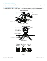
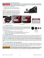
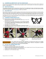
background image

©Copyright Task Force Tips LLC 2002-2020

9

LIX-030 September 4, 2020 Rev26

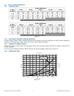
4.8 FLOW CHARACTERISTICS

4.8.1 STACKED TIPS

Table 4.8.1

4.8.2 AUTOMATIC MASTER STREAM NOZZLES

Automatic nozzles maintain a constant pressure by adjusting their opening to match the available flow. Consult the nozzle manufacturer

for maximum flow and pressure ratings. In all cases, do not exceed the operating envelope.

4.8.3 STREAM STRAIGHTENERS

Because the water must make many bends while passing through a monitor, stream quality of smooth bore nozzles is improved with a

stream straightener.
Do not use a stream straightener after a VORTEX nozzle as the stream straightener negates the vortex pattern.

4.8.4 PRESSURE LOSS

Figure 4.8.4

NOZZLE 

DIAMETER

NOZZLE PRESSURE

50 PSI

80 PSI

100 PSI

150 PSI

175 PSI

FLOW

(GPM)

REACTION

(LBS)

FLOW

(GPM)

REACTION

(LBS)

FLOW

(GPM)

REACTION

(LBS)

FLOW

(GPM)

REACTION

(LBS)

FLOW

(GPM)

REACTION

(LBS)

1-3/8”

400

150

500

240

560

300

680

440

730

520

1-1/2”

470

180

600

280

660

350

810

520

870

620

1-3/4”

640

240

810

380

910

480

1100

712

1190

840

2.00”

840

310

1060

500

1190

630

---

---

---

---

Flow exceeds rating of truck mounted monitor.

NOZZLE 

DIAMETER

(mm)

NOZZLE PRESSURE

3.5 BAR

5.5 BAR

7 BAR

10 BAR

12 BAR

FLOW

(L/min)

REACTION

(KG)

FLOW

(L/min)

REACTION

(KG)

FLOW

(L/min)

REACTION

(KG)

FLOW

(L/min)

REACTION

(KG)

FLOW

(L/min)

REACTION

(KG)

35

1500

70

1900

110

2200

140

2600

200

2800

240

38

1800

80

2300

130

2500

160

3000

230

3300

280

44

2400

110

3000

170

3400

220

4100

310

4500

370

50

3100

140

3900

220

4400

280

---

---

---

---

Flow exceeds rating of truck mounted monitor.

0.0

0.5

1.0

1.5

2.0

2.5

3.0

3.5

4.0

4.5

5.0

0

500

1000

1500

2000

2500

3000

3500

4000

4500

5000

LOSS (BAR)

FLOW (L/MIN)

CROSSFIRE Top with

Safe-Tak 1250 Base

CROSSFIRE Top

0

200

400

600

800

1000

1200

FLOW (GPM)

0

10

20

30

40

50

60

70

LOSS (PSI)

Summary of Contents for CROSSFIRE

Page 1: ...and qualified emergency services personnel for firefighting All personnel using this equipment shall have completed a course of education approved by the Authority Having Jurisdiction AHJ This instru...

Page 2: ...precautions and care of any equipment you may be called upon to use 4 It is your responsibility to be in proper physical condition and to maintain the personal skill level required to operate any equ...

Page 3: ...5 AUTOMATIC DRAIN 4 6 TRUCK MOUNT BASE 4 7 TRUCK MOUNTING OF THE PORTABLE BASE 4 8 FLOW CHARACTERISTICS 4 8 1 STACKED TIPS 4 8 2 AUTOMATIC MASTER STREAM NOZZLES 4 8 3 STREAM STRAIGHTENERS 4 8 4 PRESS...

Page 4: ...tc Choose surfaces that allow all spikes to contact the ground Do not place the monitor on top of debris objects or uneven terrain Assure that the hose is not lifting spikes off the ground If stabilit...

Page 5: ...DELS AND TERMS The CROSSFIRE monitor is available in several different models and inlet connections The following figures identify the various parts and controls of the CROSSFIRE monitor Safe Tak 1250...

Page 6: ...min 14 in 360mm N A Height Above Ground on Base 16 1 2 in 420mm N A Line of Reaction Force Above Ground 4 in 100mm N A Flow Area min 8 3 in2 5360mm2 Operating Temperature of Fluid 33 to 120 F 1 to 50...

Page 7: ...uck mount flange or portable base 1 Stop all water flow to the monitor 2 Depress the safety plunger to disengage the spring loaded pawls from the groove in the base 3 Holding the monitor by the top ca...

Page 8: ...900 lbs Prior to installation ensure that no interference exists between the monitor and other deck mounted equipment in any direction A drain valve should be provided in the riser pipe which supplies...

Page 9: ...5 PSI FLOW GPM REACTION LBS FLOW GPM REACTION LBS FLOW GPM REACTION LBS FLOW GPM REACTION LBS FLOW GPM REACTION LBS 1 3 8 400 150 500 240 560 300 680 440 730 520 1 1 2 470 180 600 280 660 350 810 520...

Page 10: ...m contacting ground 5 2 EXTENDING PORTABLE BASE LEGS The portable base legs are extended by following these steps 1 Hold the base carrying handle with one hand and grasp the end of one of the longer l...

Page 11: ...f the strap is too short to reach a suitable anchor it may be extended with strong rope or chain Keep the distance between the monitor and anchor as short as possible Remove all slack between the moni...

Page 12: ...be adjusted to open between 90 and 300 psi The pressure relief valve TFT part A1809 is set at the factory to open at 150 psi To change the relief pressure refer to the label on the bottom side of the...

Page 13: ...rge of its obligations under this limited warranty If TFT makes this election claimant shall return the equipment to TFT free and clear of any liens and encumbrances This is a limited warranty The ori...

Page 14: ...uld be cleaned and touched up with enamel paint such as Rust Oleum Replace any missing or damaged parts before returning to service Any equipment taken out of service due to failure should be returned...

Page 15: ...to equipment or injury to personnel that is a result of user service Contact the factory or visit the web site at tft com for parts lists exploded views test procedures and troubleshooting guides Perf...

Page 16: ...cklist before each use WARNING Equipment failing any part of the checklist is unsafe for use and must have the problem corrected before use or being placed back into service Operating equipment that h...

Reviews: